Vapor cooling of detonation engines

a technology of detonation engine and vapor cooling system, which is applied in the direction of turbine/propulsion fuel heating, intermittent jet plants, vessel construction, etc., can solve the problems of sudden pressure spikes and turbulence, the number of difficulties in providing, and the tbc applied to superalloys may not provide sufficient thermal protection or be sufficiently durable,

Active Publication Date: 2008-06-19
RTX CORP
View PDF26 Cites 26 Cited by
  • Summary
  • Abstract
  • Description
  • Claims
  • Application Information

AI Technical Summary

Problems solved by technology

However, detonation engines present a number of difficulties in providing cooling to engine components in a manner that is reliable and effective.
At those higher temperatures present in detonation engines, TBCs applied to superalloys may not provide sufficient thermal protection or be sufficiently durable.
Moreover, sections of detonation engines, especially sections of pulse detonation engines, can be subject to sudden pressure spikes and turbulence as a natural consequence of the detonation process.
The pressure spikes and turbulence may cause disruptive backflow or aspiration through film cooling holes, that is, acute pressure spikes or turbulence may cause hot flowpath gases to flow “backwards” into cooling holes or otherwise disrupt the film cooling.
Such backflow or aspiration may make film cooling unsuitable for use with detonation engines.

Method used


Image

  • Vapor cooling of detonation engines
  • Vapor cooling of detonation engines
  • Vapor cooling of detonation engines

Examples


Embodiment Construction

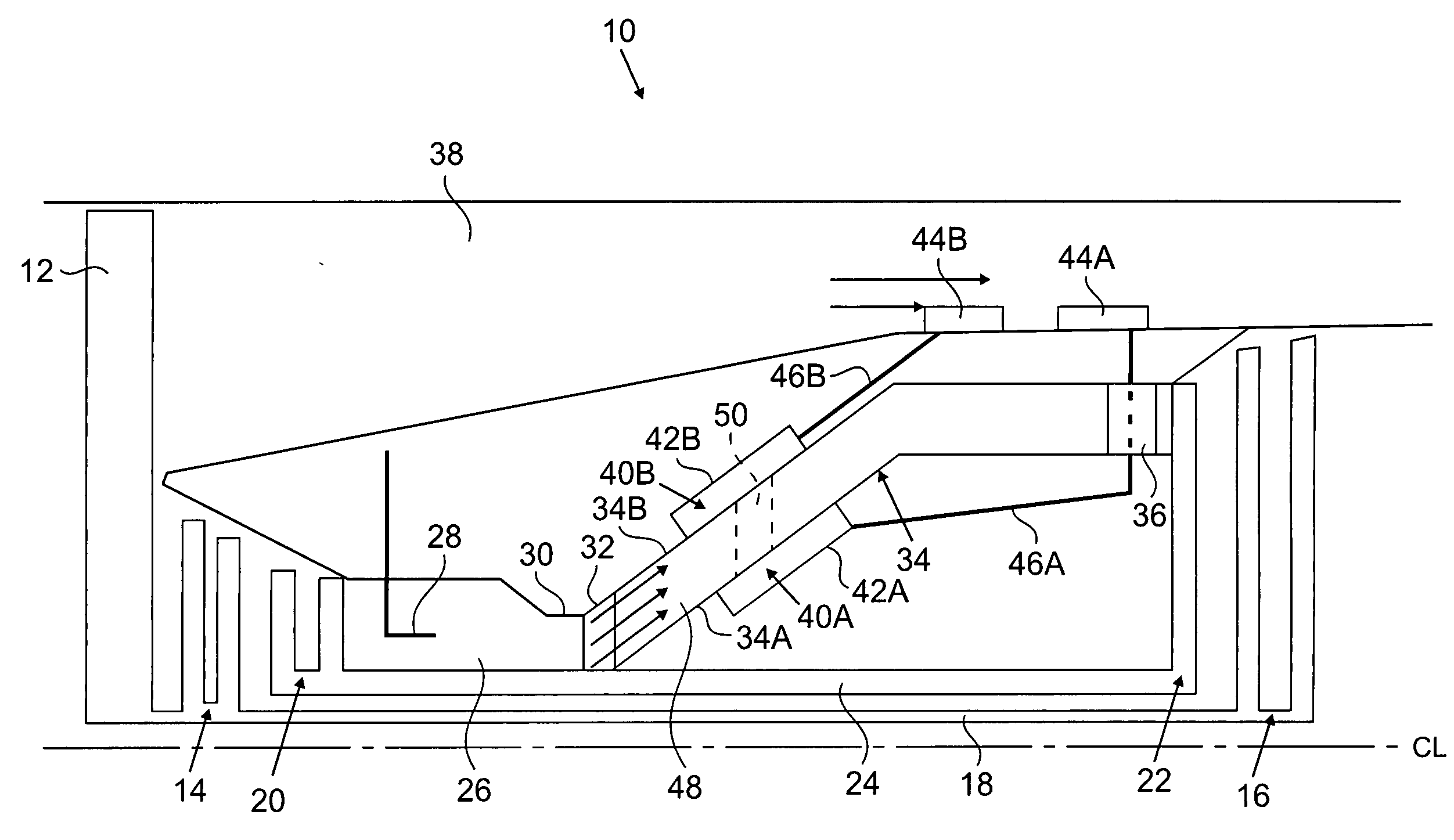
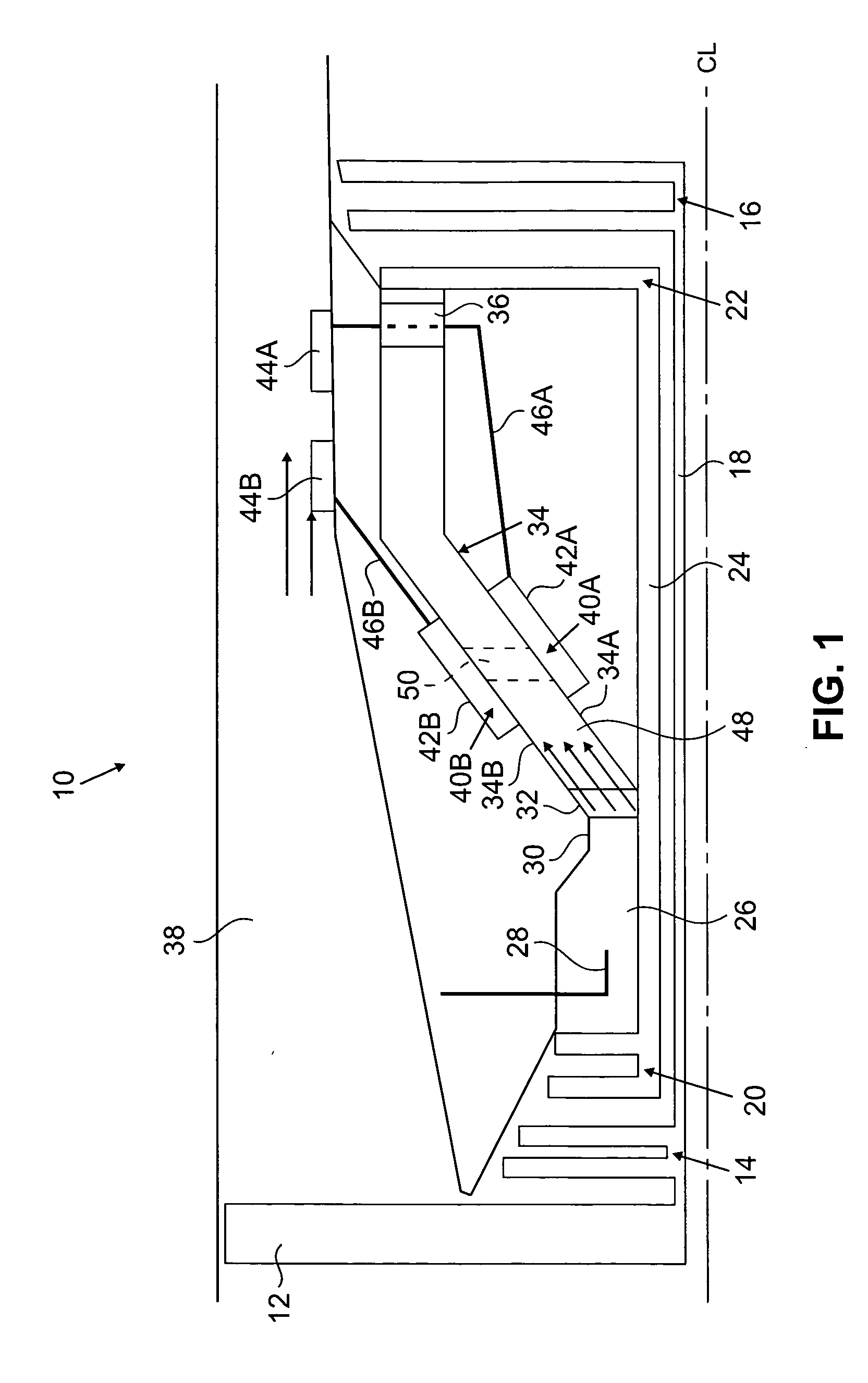
[0007]In general, the present invention relates to detonation engines that utilize a vapor cooling assembly to cool containment walls adjacent to a portion of a gas flowpath where detonation waves are typically present during operation. The vapor cooling assembly includes a vaporization section located adjacent to the gas flow path where it is desired to remove thermal energy, and a condenser section located away from the gas flow path where it is desired to expel thermal energy. The vapor cooling assembly is configured to transport thermal energy from the vaporization section to the condenser section at a relatively high rate through cyclical evaporation and condensation of a working medium sealed within the vapor cooling assembly. The condenser section can alternatively expel thermal energy to a fan bypass stream, to fuel that acts as a heat sink, or to other fluids that permit thrust recovery of that thermal energy.

[0008]FIG. 1 is a schematic illustration of a hybrid turbofan det...


PUM


Abstract

An engine cooling system includes a combustion chamber assembly configured to generate detonation waves and a first vapor cooling assembly. The combustion chamber assembly defines a flowpath between an inner liner and an outer liner. The first vapor cooling assembly includes a vaporization section located adjacent to the flowpath and a condenser section spaced from the flowpath, and is configured to transport thermal energy from the vaporization section to the condenser section through cyclical evaporation and condensation of a working medium sealed within the first vapor cooling assembly.

Description

BACKGROUND OF THE INVENTION[0001]The present invention relates to systems for cooling detonation engines, and more particularly to vapor cooling systems for cooling detonation engines.[0002]Known gas turbine engines have utilized superalloys, thermal barrier coatings (TBCs), and film cooling schemes in order to provide combustion chamber structures that can operate efficiently at high temperatures and pressure while still maintaining a relatively long component lifespan. In order to improve engine efficiency, it has been desired to develop engines that utilize detonation in addition to or instead of slower speed, non-detonative combustion. Utilization of detonation schemes (e.g., pulse detonation or continuous detonation) takes advantage of the thermodynamic benefits of fuel burn recovery, to increase engine fuel efficiency.[0003]However, detonation engines present a number of difficulties in providing cooling to engine components in a manner that is reliable and effective. In conve...

Claims


Application Information

Patent Timeline
Patent Type & Authority Applications(United States)
IPC IPC(8): F01P9/02
CPCF01D25/12F02C5/02F02C7/16F05D2260/2322F02K7/02F02C7/224F05D2220/40F02C7/18
Inventor NORRIS, JAMES W.TWELVES, WENDELL V.
Owner RTX CORP
Why Eureka
Try Eureka