
Fuel Supply System

Inactive Publication Date: 2008-06-19
NISSAN MOTOR CO LTD
View PDF13 Cites 66 Cited by
  • Summary
  • Abstract
  • Description
  • Claims
  • Application Information

AI Technical Summary

Benefits of technology

[0010]The present invention has been made in consideration for the above-described problems. It is an object of the present invention to provide a fuel supply system including a fuel reformer capable of exerting excellent reforming performance in the liquid phase without installing the insulating film between the electrodes, and including a fuel supply device for efficiently supplying the produced hydrogen-containing gas and the like to an engine.

Problems solved by technology

However, such a fuel reformer has a problem as below because the insulating film is provided therein.
Specifically, bubbles of the gas generated by the reforming are sometimes attached onto a portion of the pinhole which the insulating film includes, and there is an apprehension that a stable electric discharge cannot be maintained for a sufficient time.
Moreover, following the installation of the insulating film, a shape of a reaction container and a supply mode of the liquid fuel are restricted, and there is an apprehension that the output of the electric discharge cannot be sufficiently increased.
Furthermore, the installation itself of the insulating film will make the production cost higher.

Method used


Image

  • Fuel Supply System
  • Fuel Supply System
  • Fuel Supply System

Examples


example 1

[0077]The iso-octane was reformed in a liquid phase by using the fuel reformer of the mode shown in FIG. 7, and the hydrogen-containing gas was produced.

[0078]The temperature inside the reaction chamber 40 was maintained at 30° C., and a voltage of 5 kV was applied between the electrodes (50, 60) by the activation of the voltage applying unit 6. In such a way, the electric discharge was stably generated between the electrodes (50, 60), the iso-octane was reformed, and the hydrogen-containing gas was produced.

[0079]The produced gas was emitted to the outside of the reaction container 40 p through the gas collecting portion 62 and the reformed fuel supply passage 3b. The hydrogen-containing gas thus emitted was collected, and a component composition of the gas concerned was analyzed by gas chromatography. Moreover, a production rate of the hydrogen-containing gas was determined. The component composition of the hydrogen-containing gas, which was obtained by the analysis, and the produ...

example 2

[0080]The iso-octane was reformed in the liquid phase by using the fuel reformer of the mode shown in FIG. 8 to generate the hydrogen-containing gas.

[0081]The fuel reformer 4 shown in FIG. 8 is similar to the fuel reformer 4 of the mode shown in FIG. 7 except that the reaction container 40 includes the three pairs of electrodes (50A and 60a, 50B and 60B, and 50C and 60C). Specifically, of the three pairs of electrodes, the electrodes (50A, 50B and 50C) as ones of the three pairs are connected to the voltage applying unit 6. Then, the surfaces of the electrodes connected to the voltage applying unit 6 and located in the inside of the reaction container 40, are coated with the epoxy resin as the insulating material, and form the coated portions 52. Moreover, the exposed portions 54 with a diameter of 0.5 mm, which are not coated with the epoxy resin, are present on the centers of the surfaces opposite to the other electrodes (60A, 60B and 60C) in the surfaces of these electrodes. Then...


PUM

PropertyMeasurementUnit
Fractionaaaaaaaaaa
Areaaaaaaaaaaa
Temperatureaaaaaaaaaa

Abstract

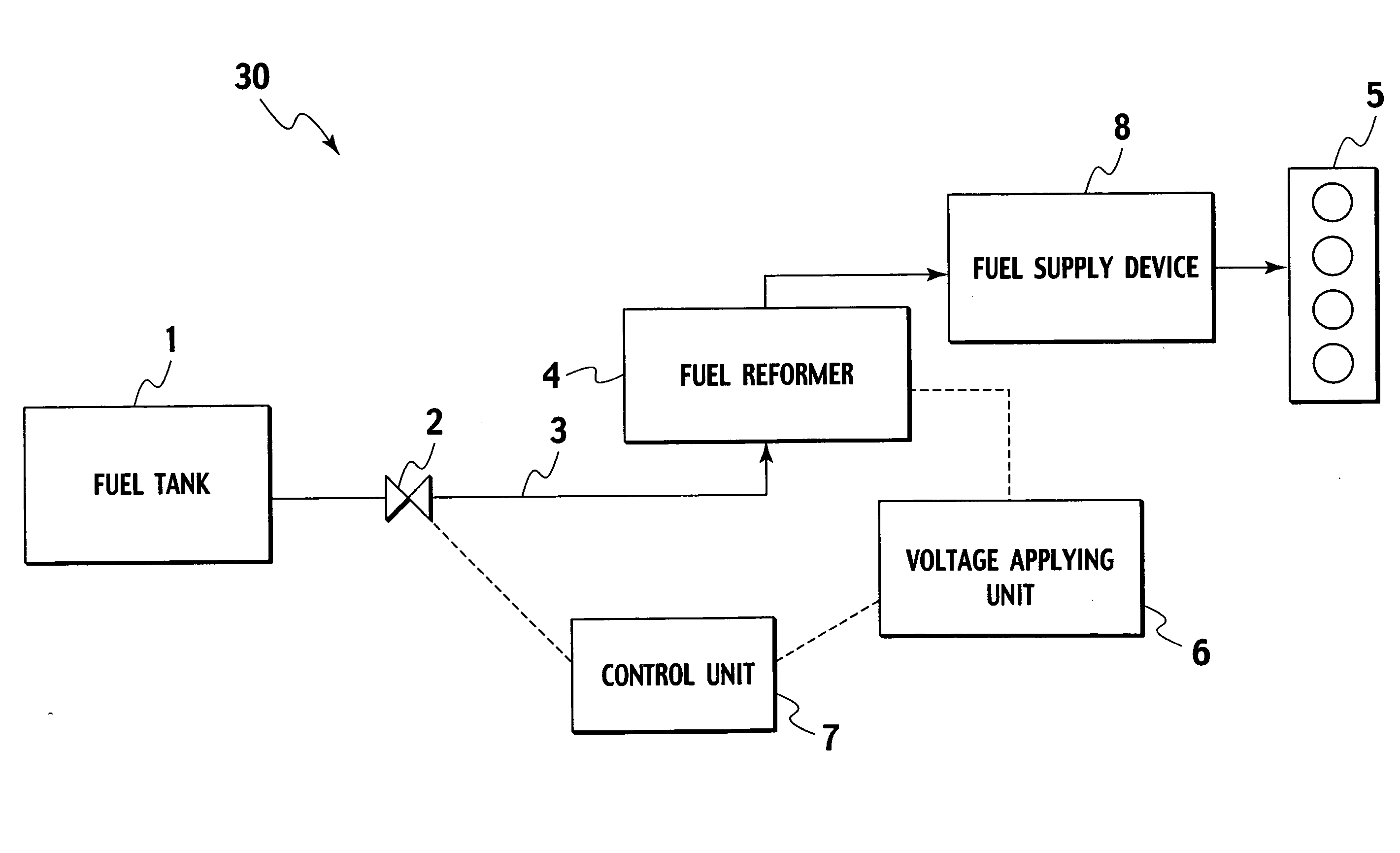
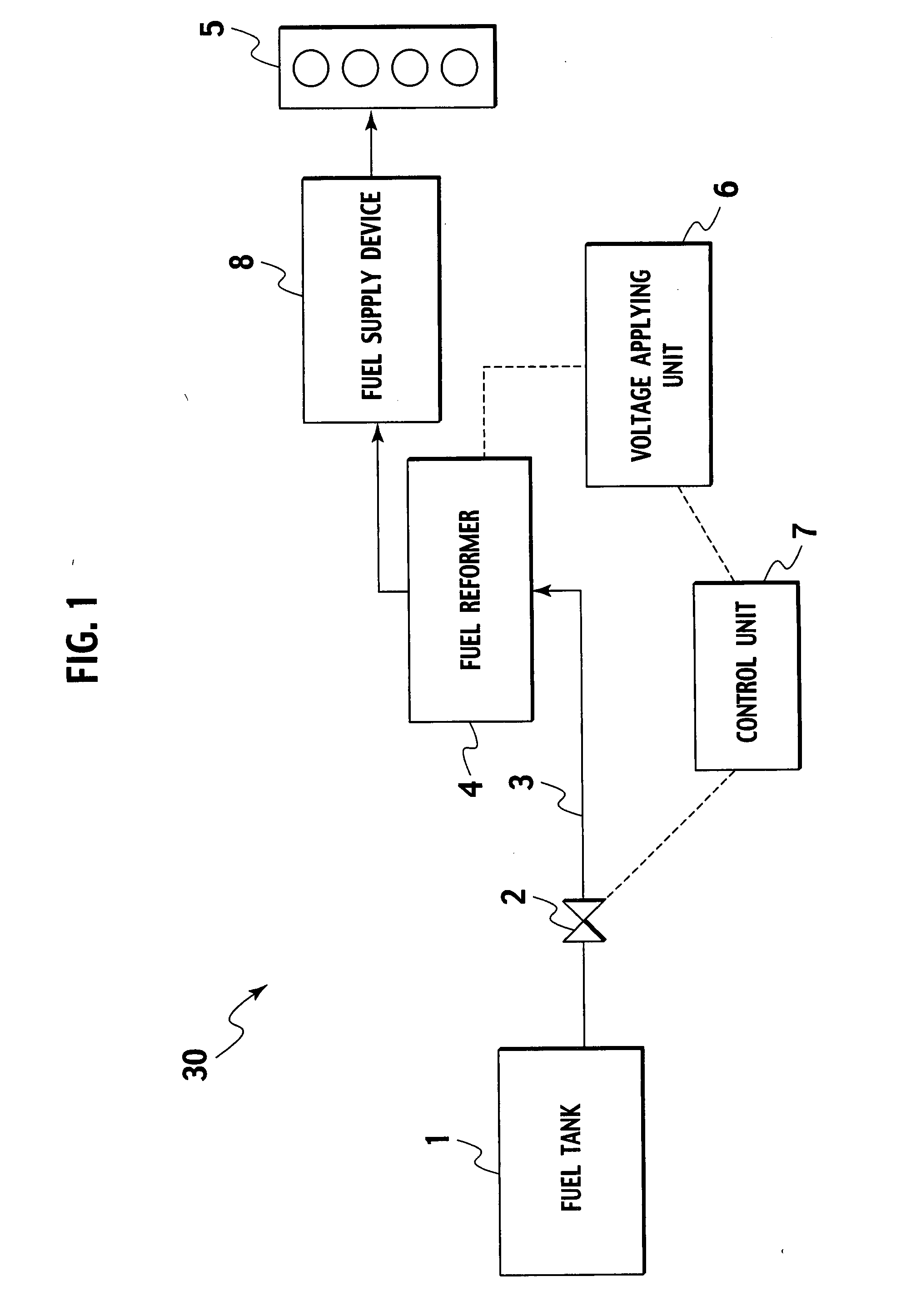
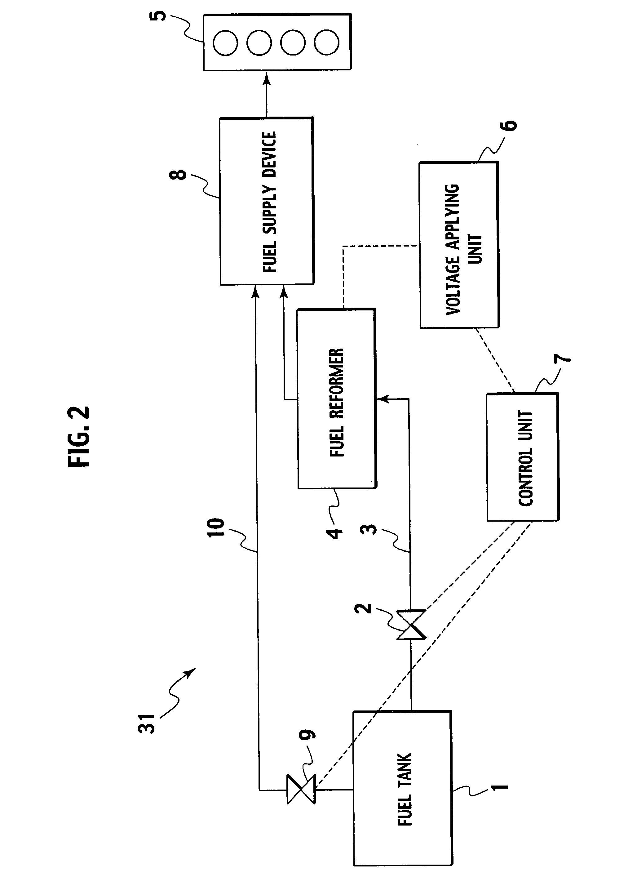
A fuel supply system of the present invention is characterized by including: a fuel reformer (4) for producing a reformed gas-containing fuel by causing discharge in a raw liquid fuel; and a fuel supply device (8) for supplying the reformed gas-containing fuel or a mixture of the reformed gas-containing fuel and the raw fuel into a combustion chamber of an engine (5).

Description

TECHNICAL FIELD[0001]The present invention relates to a fuel supply system. More specifically, the present invention relates to a fuel supply system including a fuel reformer for producing hydrogen-containing gas by an electric discharge in a fuel liquid, and a fuel supply device for supplying such a reformed fuel to an engine.BACKGROUND ART[0002]In recent years, various researches and developments have been conducted regarding production of hydrogen-containing gas by fuel reforming in order to utilize the hydrogen-containing gas for various industrial purposes such as a fuel of a fuel cell and hydrogenation of a variety of organic compounds.[0003]As a fuel for producing the hydrogen-containing gas, hydrocarbons such as methane and gasoline and alcohols such as methanol are used in general. In a fuel reforming reaction, there are steam reforming, partial oxidation reforming, and autothermal reforming in which the steam reforming and the partial oxidation reforming are combined. Reac...

Claims


Application Information

Patent Timeline
IPC IPC(8): F02M21/00F02B43/08F02D41/04
CPCC01B3/323F02D19/0671C01B2203/0227C01B2203/0861C01B2203/1064C01B2203/169C01B2203/84C10L3/00F02D19/081F02M21/06F02M27/04F02M37/0064Y02T10/36Y02T10/32F02D19/0644C01B3/342Y10S123/12Y02T10/30
Inventor HAGA, FUMIHIRO
Owner NISSAN MOTOR CO LTD
Features
  • Generate Ideas
  • Intellectual Property
  • Life Sciences
  • Materials
  • Tech Scout
  • Unparalleled Data Quality
  • Higher Quality Content
  • 60% Fewer Hallucinations
Learn More