Hydrogen Storage Tank and Manufacturing Method for the Same

a technology of hydrogen storage tank and hydrogen storage tank, which is applied in the direction of electrochemical generators, transportation items, containers, etc., can solve the problems of increasing the amount of hydrogen that can be stored, increasing the risk of leakage, and increasing the risk of carbon dioxide emitted from vehicles, so as to reduce the weight of containers and achieve good balance , the effect of high reliability

Inactive Publication Date: 2008-06-19
SAM TECHOLOGY +1
View PDF6 Cites 19 Cited by
  • Summary
  • Abstract
  • Description
  • Claims
  • Application Information

AI Technical Summary

Benefits of technology

[0029]According to the present invention, a cartridge which is filled with a hydrogen occluding substance is contained within an integrally molded liner which is seamless and made of a metal, and the liner torso portion made of a metal can be maintained so as not to make any contact, and therefore, a safe hydrogen storage tank in a highly reliable form where it is difficult for fatigue failure to occur can be provided.
[0030]In addition, the inner surface of the integrally molded metal liner can be maintained so as not to make any contact, and thereby, it becomes unnecessary to inspect the inner surface of the liner torso portion, which is, in actuality, difficult to carry out after the completion of the liner.
[0031]Furthermore, the cartridge is supported at both ends in the structure, and therefore, can be supported and has good balance. In addition, the recess of the support plug absorbs the thermal expansion, the thermal contraction, and the movement forward and backward, which occurs at the time of the application of pressure, of the cartridge, and therefore, malfunctioning due to thermal strain or the like can be prevented.
[0032]Furthermore, a hydrogen occluding substance can be put into the cartridge via the support plug flow path and the cartridge flow path so that the cartridge is filled with the hydrogen occluding substance after the completion of the hydrogen storage tank having a structure where the cartridge is contained within the liner, and therefore, it becomes unnecessary to pay attention to the hydrogen occluding substance in order to make sure that it does not make contact with moisture during the manufacturing process for the tank (for example, during heat treatment).
[0033]In the above described invention, the liner may be formed of an aluminum alloy, and a fiber reinforced resin layer may be formed on the outside of the liner.
[0034]A reduction in the weight of the container can be achieved by using an aluminum alloy for the liner, and the strength can be reinforced so that safety and reliability can be increased by forming a fiber reinforced resin on the outside of the liner.

Problems solved by technology

In recent years, together with global warming, carbon dioxide emitted from vehicles has become a problem, and efforts have been made to reduce the amount of carbon dioxide emissions.
In this case, the higher the pressure for filling the hydrogen gas is, the greater the amount of hydrogen that can be stored becomes, and airtightness involving the flange portion having a large diameter is not sufficient under high pressure, and therefore, there is a possibility of leakage.
In this case, the smaller the diameter of the divided portion is, the smaller the force that is applied to the divided portion as a result of the pressure within the container is, and therefore, the easier it becomes to increase sealing, but the diameter of the divided portion cannot be made smaller than the outer diameter of the hydrogen occluding unit, and therefore, the possibility of leakage occurring due to high pressure at a certain level or higher, which exceeds the limit of the withstanding pressure of the sealing material or the like, becomes high.
That is to say, the fatigue strength should be increased through heat treatment because the internal pressure increases and decreases when the filling of the hydrogen occluding alloy with hydrogen and the releasing of hydrogen are repeated, and therefore, the tank container expands and contracts, and thus, metal fatigue gradually increases.

Method used


Image

  • Hydrogen Storage Tank and Manufacturing Method for the Same
  • Hydrogen Storage Tank and Manufacturing Method for the Same
  • Hydrogen Storage Tank and Manufacturing Method for the Same

Examples


Embodiment Construction

(Structure of Hydrogen Storage Tank)

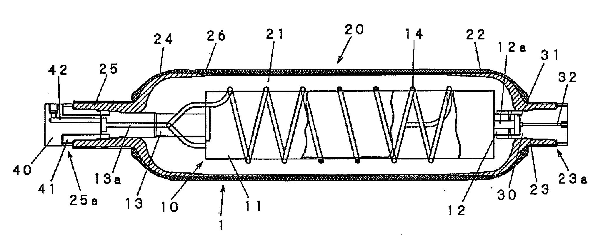
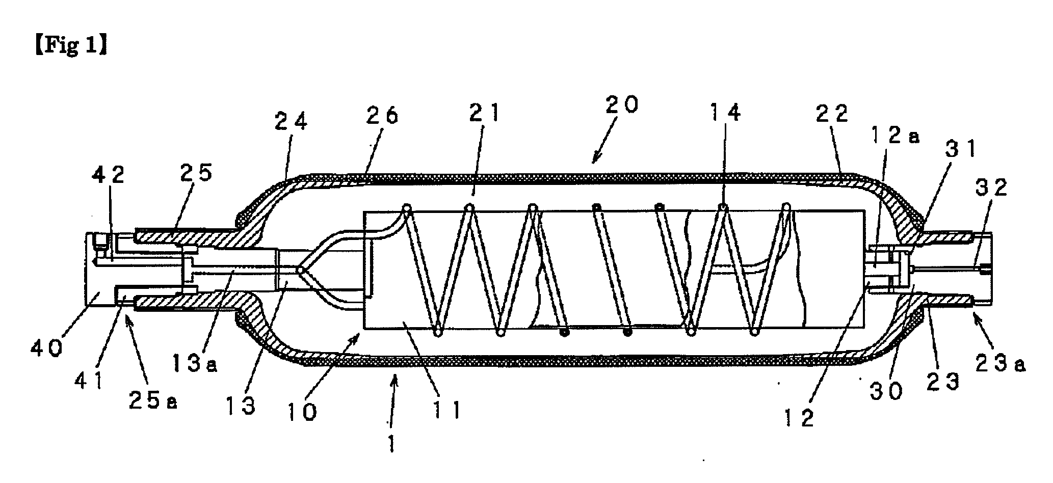
[0069]In the following, the structure of the hydrogen storage tank according to the present invention is described in reference to the drawings. FIG. 1 is a cross sectional diagram showing the hydrogen storage tank according to one embodiment of the present invention (here, the cartridge portion, of which a portion is removed, is not shown as a cross section, but as a front diagram).

[0070]This hydrogen storage tank 1 is mainly formed of a cartridge 10, a liner 20, a support plug 30 and a sealing plug 40.

[0071]The cartridge 10 is formed of a main body portion 11 in cylindrical form, a free side axial portion 12, which is provided so as to protrude in the direction of the axial line from one end side of the main body portion 11, and a fixed side axial portion 13, which is provided so as to protrude in the direction of the axial line from the other end side of the main body portion 11. The main body portion 11 is hollow so it can be filled with a hyd...


PUM

PropertyMeasurementUnit
pressureaaaaaaaaaa
pressureaaaaaaaaaa
volumeaaaaaaaaaa

Abstract

[Object] A safe hydrogen storage tank in a highly reliable form where it is difficult for fatigue failure to occur is provided as a hydrogen storage tank where a cartridge is filled with a hydrogen occluding substance and contained within an integrally molded liner made of a metal.
[Means for Achieving Object] A cartridge 10 is formed of a cartridge main body portion 11, a fixed side axial portion 13 and a free side axial portion 12, and an integrally molded liner 20 which is seamless is formed of a liner torso portion 21, a fixed side end portion 25 where a fixed side opening 25a is created via a portion in dome form 24 and a free side end portion 23 where a free side opening 23a for supporting a support plug 30 is created via a portion in dome form 22 in order to support a free side axial portion 12a, in such a manner that the fixed side opening 25a fixes and supports the fixed side axial portion 13 and is sealed by a sealing plug 40 while the free side opening 23a is sealed by the support plug 30, and the free side axial portion 12 is inserted into and supported by the recess 31 created in the support plug 30 so as to be moveable forward and backward in the direction of the axial line.

Description

BACKGROUND OF THE INVENTION[0001]1. Field of the Invention[0002]The present invention relates to a hydrogen storage tank which is mainly used as a hydrogen fuel tank for an automobile, and in particular, to a hybrid type hydrogen storage tank where a cartridge is filled with a hydrogen occluding substance and contained within a tank.[0003]2. Description of the Related Art[0004]In recent years, together with global warming, carbon dioxide emitted from vehicles has become a problem, and efforts have been made to reduce the amount of carbon dioxide emissions. Fuel battery automobiles use power which is generated through an electrochemical reaction between hydrogen and oxygen as an energy source and does not emit carbon dioxide in the reaction process, and therefore, have been developed as automobiles for the next generation. Fuel battery automobiles are equipped with a hydrogen storage tank which works as a supply source of hydrogen, which is the fuel. It is important for the hydrogen ...

Claims


Application Information

Patent Timeline
Patent Type & Authority Applications(United States)
IPC IPC(8): B65D25/14
CPCF17C1/00F17C2270/0178F17C2221/012F17C2270/0184Y02E60/321F17C2201/0109F17C2201/056F17C2201/058F17C2203/0604F17C2203/0619F17C2203/0646F17C2203/0648F17C2203/0663F17C2205/0397F17C2209/2109F17C2209/2181F17C2209/221F17C2223/0123F17C2223/036F17C2201/0104Y02E60/32
Inventor SAKAGUCHI, YOSHIKINISHIWAKI, HIDEAKISAKAGUCHI, NAOKIYAMAMOTO, TAKESHITSUNOKAKE, SHIGERUFUURA, TATSUYAWATANABE, SHOGOMAEDA, YASUMASA
Owner SAM TECHOLOGY
Why Eureka
Try Eureka