
Optical transceiver using heterodyne detection and a transmitted reference clock

a transceiver and heterodyne technology, applied in electromagnetic transceivers, transmission monitoring/testing/fault-measurement systems, transmission monitoring, etc., can solve the problems of phase stability lasers that are both bulky and expensive, and the transmission data error is further intensified. to achieve the effect of reducing the effect of phase nois

Inactive Publication Date: 2008-06-19
FORSTER ENERGY
View PDF18 Cites 40 Cited by
  • Summary
  • Abstract
  • Description
  • Claims
  • Application Information

AI Technical Summary

Benefits of technology

Significantly reduces phase noise in coherently modulated optical heterodyne communications systems, enhancing data transmission efficiency without the need for expensive or bulky components.

Problems solved by technology

Upcoming widespread deployment of new bandwidth-intensive services, such as xDSL, will only further intensify this demand.
Relative phases errors in the absolute phase references generally results in errors in the transmitted data.
However, phase-stable lasers are both bulky and expensive, making them impractical for commercial applications.
Complex phase-locking circuits are likewise expensive and difficult to implement.
Furthermore, both solutions significantly raise the cost and complexity of the system.

Method used


Image

  • Optical transceiver using heterodyne detection and a transmitted reference clock
  • Optical transceiver using heterodyne detection and a transmitted reference clock
  • Optical transceiver using heterodyne detection and a transmitted reference clock

Examples


embodiment 490

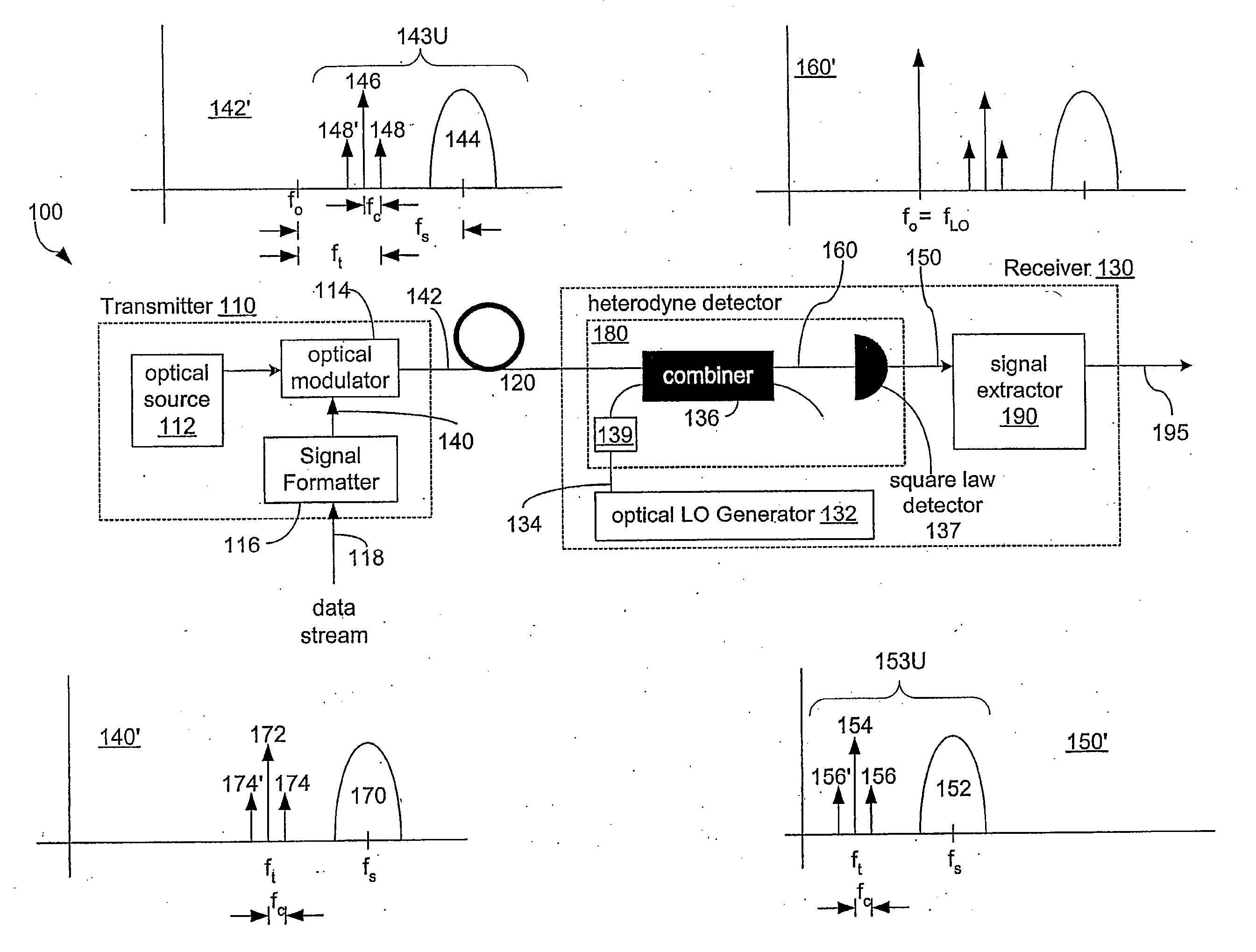
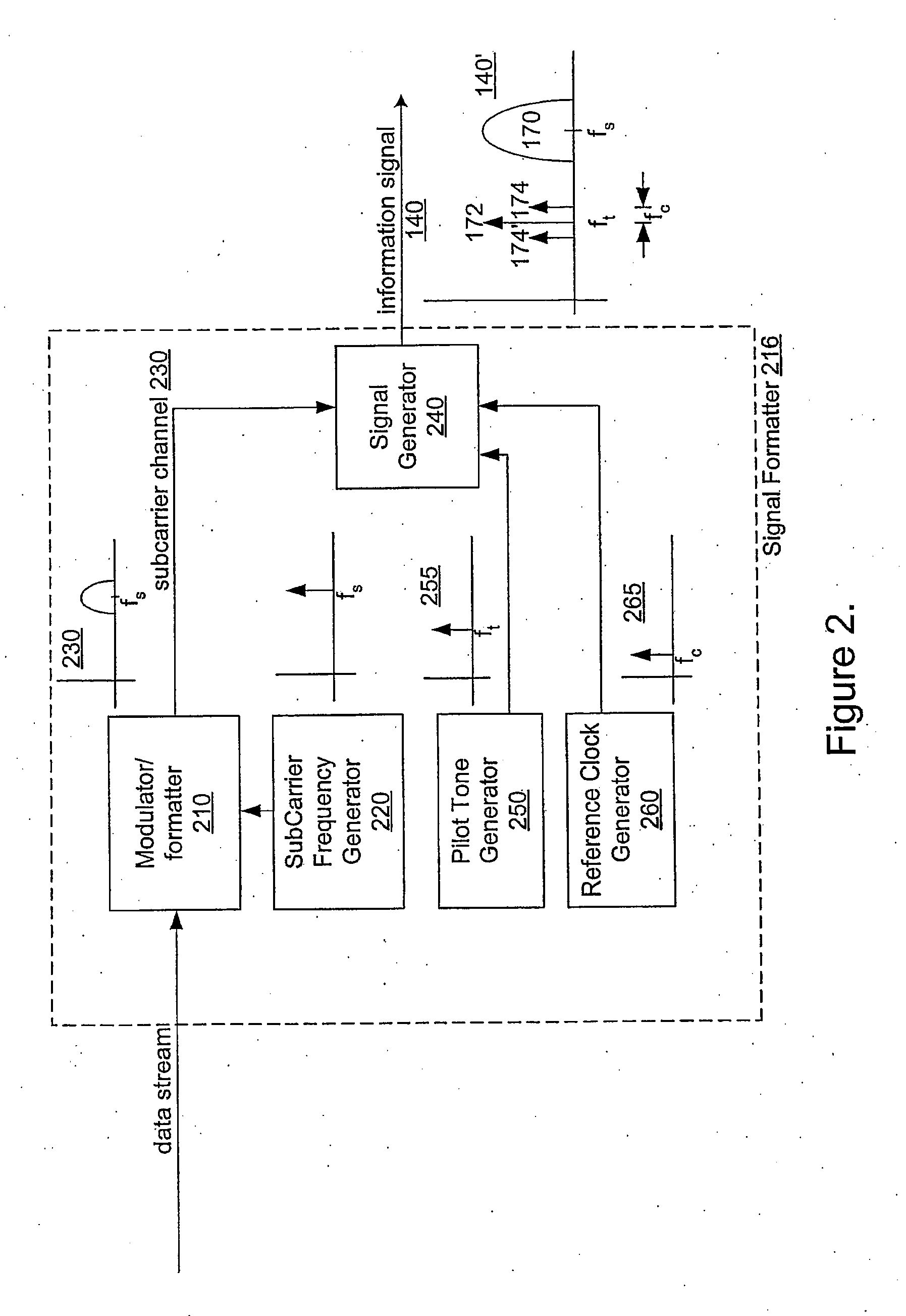
[0055]FIG. 4 is a block diagram of an embodiment 490 of signal extractor 190. Signal extractor 490 includes an information signal splitter 405, coupled to a local oscillator generator 450 and to a demodulator 460. Local oscillator generator 450 is also coupled to demodulator 460. In one embodiment, information signal splitter 405 includes an electrical signal splitter 410, a tone recovery arm 420, a reference clock recovery arm 430, and a data recovery arm 440. Electrical signal splitter 410 is configured to receive electrical signal 150 and is coupled to each recovery arm 420, 430, and 440. Tone recovery arm 420 and clock recovery arm 430 are both coupled to local oscillator generator 450. Data recovery arm 440 and local oscillator generator 450 each output to demodulator 460 which outputs recovered data stream 195.

[0056]Signal extractor 490 operates as follows. Electrical signal 150 is received from heterodyne detector 180 by electrical signal splitter 410. Electrical signal split...

embodiment 650

[0062]FIG. 6 is a block diagram of an embodiment 650 of local oscillator generator 450. Local oscillator generator 650 includes a frequency multiplier 610 coupled to a local oscillator combiner 620. In one embodiment, local oscillator combiner 620 includes signal multiplier 630 coupled to band pass filter 640.

[0063]Local oscillator generator 650 operates as follows. Frequency multiplier 610 receives reference clock signal 435 at frequency fC. Frequency multiplier 610 generates a multiplied clock 615 which is at a frequency which is a fractional multiple N of the frequency of the incoming reference clock 435. In other words the frequency of reference clock signal 435 is increased from fC to N·FC. In a preferred embodiment N is an integer factor. However, any reproducible factor can be chosen. Local oscillator combiner 620 combines pilot tone 425 and multiplied clock 615 to generate local oscillator 455 having the same phase noise and group delay as subcarrier channel 445. In a prefer...


PUM


Abstract

A heterodyne communication system uses coherent data modulation that is resistant to phase noise. In particular, a pilot tone and reference clock signal are transmitted along with the modulated data to form the basis of an electrical demodulation local oscillator at the receiver. The pilot tone and / or reference clock signal carry phase noise which is correlated with the phase noise in the data signal. At the receiver, the local oscillator is generated from the pilot tone and reference clock signal in a manner so that the local oscillator also has phase noise which is correlated with the phase noise in the data signal. Thus, the two noise components can be used to cancel each other during demodulation of the data signal using the local oscillator.

Description

BACKGROUND OF THE INVENTION[0001]1. Field of the Invention[0002]This invention relates generally to optical fiber communications and, more particularly, to a reduction in the effects of phase variations introduced by the optical carrier.[0003]2. Description of the Related Art[0004]As the result of continuous advances in technology, particularly in the area of networking, there is an increasing demand for communications bandwidth. For example, the growth of the Internet, home office usage, e-commerce and other broadband services is creating an ever-increasing demand for communications bandwidth. Upcoming widespread deployment of new bandwidth-intensive services, such as xDSL, will only further intensify this demand. Moreover, as data-intensive applications proliferate and data rates for local area networks increase, businesses will also demand higher speed connectivity to the wide area network (WAN) in order to support virtual private networks and high-speed Internet access. Enterpri...

Claims


Application Information

Patent Timeline
Patent Type & Authority Applications(United States)
IPC IPC(8): H04B10/00
CPCH04B10/40H04B10/64H04B10/6165
Inventor LI, JINEWELL, LAURENCE J.VO, TINYEE, TING K.CHANG, PETER H.MCELHENY, ROBERT K.
Owner FORSTER ENERGY
Learn More