Engine system and a method for a combustion inhibition regeneration of an exhaust gas treatment device in a such system

a technology of exhaust gas treatment device and engine system, which is applied in the direction of electrical control, process and machine control, etc., can solve the problems of reducing the capacity of converter, and reducing the efficiency of catalyst exhaust gas treatment device sulfur, etc., to achieve fast and precise control of reduce the amount of fuel injected while ignition inhibition is inhibited, and reduce the temperature of the exhaust gas treatment device

Inactive Publication Date: 2008-06-26
FORD GLOBAL TECH LLC
View PDF5 Cites 13 Cited by
  • Summary
  • Abstract
  • Description
  • Claims
  • Application Information

AI Technical Summary

Benefits of technology

[0017]In one embodiment, the method includes determining the temperature of the exhaust gas treatment device, the amount of fuel allowed into the at least one of the cylinders, in which combustion is inhibited, being controlled in dependence on the temperature of the exhaust gas treatment device. For example, if, during the regeneration, it is desired to decrease the exhaust gas treatment device temperature, the amount of fuel injected while ignition is inhibited can be decreased, and vice versa. The control of the injected amount of fuel provides an advantageous manner of monitoring and controlling the exhaust gas treatment device temperature. This control can be used individually, or in combination with said control of the number of cylinders into which fuel is allowed while combustion is inhibited. Thereby, the control of the number of cylinders into which fuel is allowed, while combustion is inhibited, can be used as for a coarse temperature control, and the control of the injected amount of fuel, in the respective cylinder in which fuel is allowed, can be used for a fine temperature control. This provides a fast and precise control of the exhaust gas treatment device temperature.
[0018]Preferably, the method includes controlling air flow so as to control the combustion in the exhaust gas treatment device during the combustion inhibition exhaust gas treatment device regeneration. By adjusting the air flow, for example based on the flow of fuel injected, it can be secured that a combustible air / fuel mixture is provided to the catalytic converter during the regeneration action. Also, controlling the combustion in the exhaust gas treatment device could comprise controlling a location or a region of a maximum temperature in the exhaust gas treatment device. Thereby, as explained closer below, the air flow can be used to control the temperature distribution in a longitudinal direction of the catalytic converter. By changing, during the sulfur regeneration, the location of the maximum temperature, it is possible to obtain a particularly thorough regeneration, since it can be secured that the temperature is increased sufficiently for sulfur deposit removal throughout the entire catalytic converter. Also, moving the maximum temperature in this way further reduces the risk of damaging the catalytic converter by high temperature exposure. Specially, the risk of excessive temperatures in an upstream end of the catalytic converter can be substantially reduced, so that catalytic converter damage can be effectively avoided.

Problems solved by technology

A known problem with catalytic converters is that certain substances can remain, for example by physical or chemical adsorption, on internal surfaces of the converters, and reduce the capacity of the converters.
Such adsorption is known as catalytic converter poisoning.
The sulfur reduces efficiency of the catalyst exhaust gas treatment devices.
In the engine combustion process, the sulfur is converted to sulfur oxides (SOx), which adsorbs strongly to internal surfaces of the catalyst and therefore reduces its exhaust gas treatment capacity.
A disadvantage with this method is that it requires an additional component in the form of an air pump for the introduction of the secondary air.
Apart from adding to the complexity and the cost of the engine system, such an air pump creates a noise, which can be disturbing to drivers and passengers in a vehicle in which the pump is installed.
Further, a high exhaust gas pressure can give an excessive load to the air pump.
Also, since air, according to said patent publication, is injected downstream of the engine, relatively close to the catalytic converter, there is a great possibility that the fuel and air will not be fully mixed when reaching the catalytic converter.
This reduces the efficiency of the regeneration method, and can cause concentration of fuel, which may result in degradation of the catalytic converter.
However, the proposed solution increases the fuel consumption.
Also, since the energy for heating the catalytic converter is transported thermally, there are substantial energy losses between the engine and the catalytic converter in the form of temperature decrease.
In the case of the catalytic converter being provided relatively far from the engine, the energy losses may be such that no, or an insufficient result is provided by the measure.
Also, in the case of the engine system being equipped with an exhaust turbo charger, the energy losses at the delayed ignition regeneration measure are further increased.

Method used


Image

  • Engine system and a method for a combustion inhibition regeneration of an exhaust gas treatment device in a such system
  • Engine system and a method for a combustion inhibition regeneration of an exhaust gas treatment device in a such system
  • Engine system and a method for a combustion inhibition regeneration of an exhaust gas treatment device in a such system

Examples


Embodiment Construction

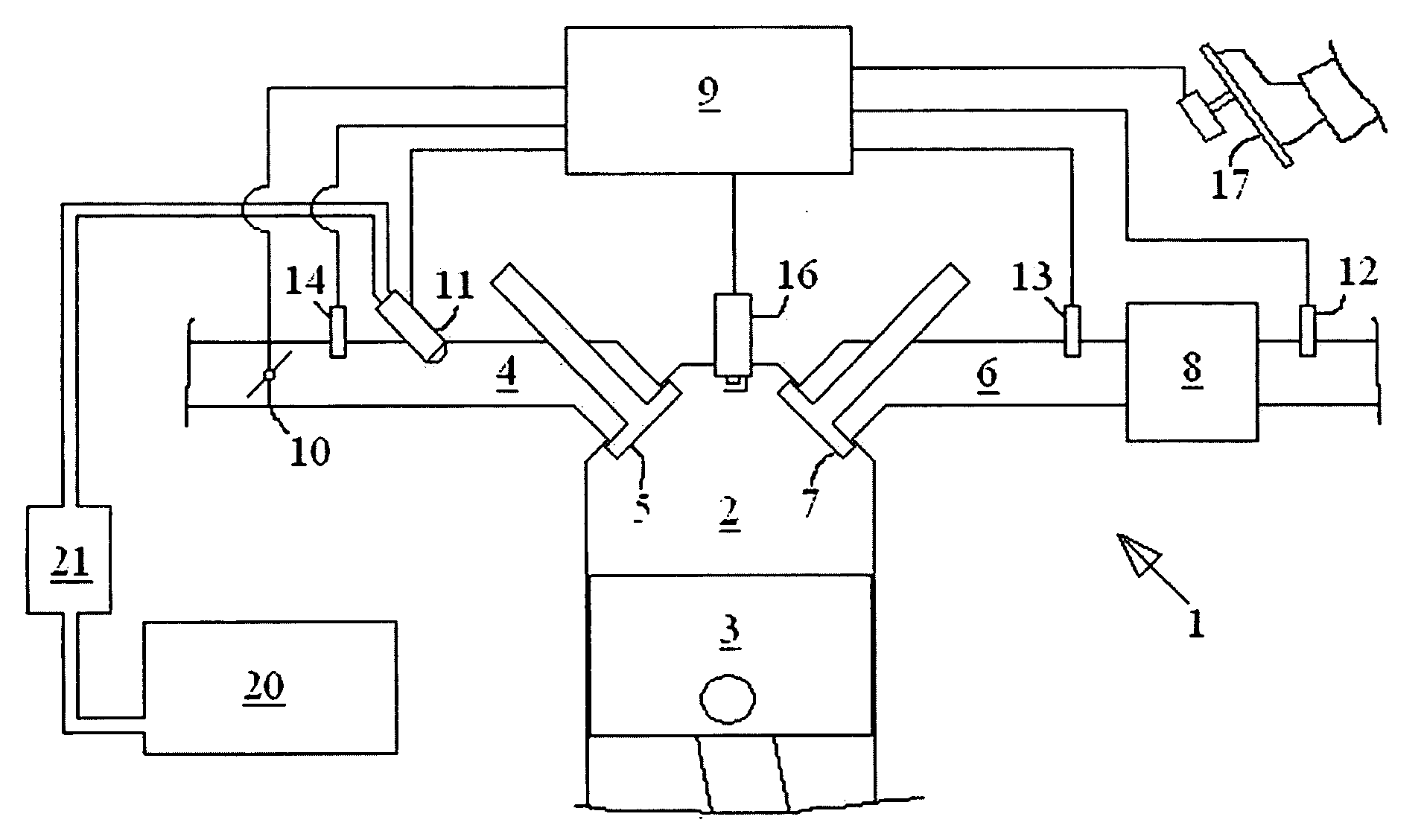
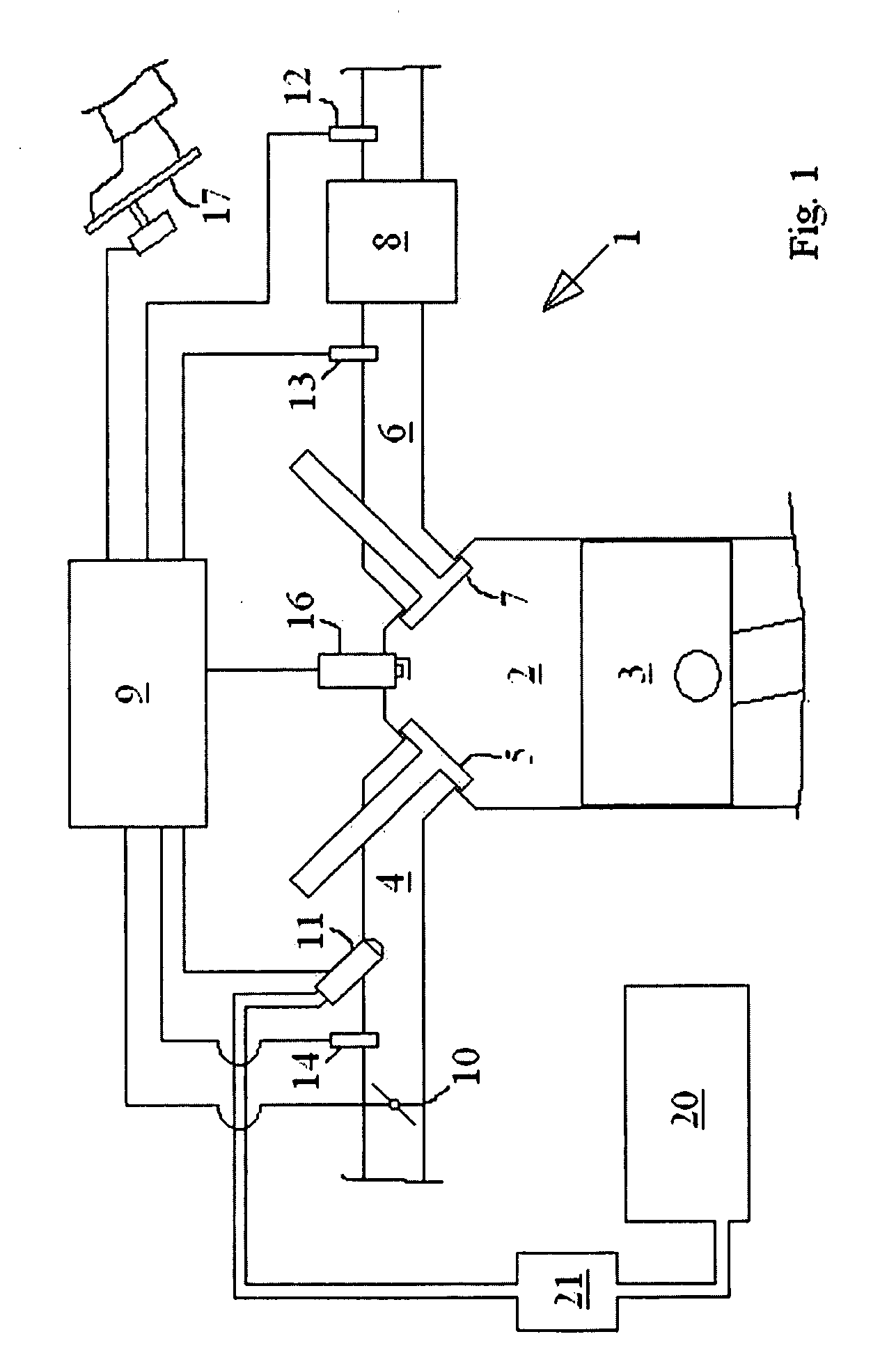
[0024]FIG. 1 shows a schematic view of parts of an exemplary vehicle engine system 1 comprising an internal combustion engine. The engine comprises four cylinders 2, of which only one is shown in FIG. 1, each with a reciprocating piston 3. It should be noted that the invention is applicable to engines with any number of cylinders. Communication between each cylinder 2 and an inlet duct 4 is controlled by at least one respective inlet valve 5, and communication between each cylinder 2 and an exhaust duct 6 is controlled by at least one respective exhaust valve 7. Downstream from the cylinders 2, an exhaust gas treatment device 8, in the form of a catalytic converter, is provided.

[0025]The engine system 1 also comprises an engine control unit (ECU) 9, which can be provided as one unit, or as more than one logically interconnected physical units. The ECU 9 is adapted to control air flow control system comprising a throttle valve 10, and fuel injection system 11 comprising at least one ...


PUM


Abstract

A method and a system for regenerating an exhaust gas treatment device in an internal combustion engine having at least one cylinder are presented. The method comprises regenerating the device by inhibiting combustion in at least one of the engine cylinders and controlling the fuel injection system so that fuel is allowed into at least one of the cylinders in which combustion is inhibited.

Description

TECHNICAL FIELD[0001]The present invention relates to a method for regenerating an exhaust gas treatment device for an internal combustion engine comprising at least one cylinder and fuel injection system.BACKGROUND OF THE INVENTION[0002]Modern vehicles are equipped with exhaust gas treatment devices, known as catalytic converters, that convert regulated substances such as hydrocarbons (HC), carbon monoxide (CO) and nitrogen oxides (NOx) into substances such as carbon dioxide (CO2), nitrogen (N2) and water (H2O). A known problem with catalytic converters is that certain substances can remain, for example by physical or chemical adsorption, on internal surfaces of the converters, and reduce the capacity of the converters. Such adsorption is known as catalytic converter poisoning. For example, fuels, whether gasoline or diesel, for vehicle internal combustion engines, contain a relatively high amount of sulfur, typically depending on in which state or region they are provided. The sul...

Claims


Application Information

Patent Timeline
Patent Type & Authority Applications(United States)
IPC IPC(8): F01N3/00F02D17/02
CPCF01N3/206F02D37/02F02D41/0002F02D41/008F02D41/025Y02T10/42F02D41/1446F02D41/266F02P9/002Y02T10/26F02D41/027Y02T10/12Y02T10/40Y02A50/20
Inventor HERMANSSON, JONASVOLLMER, NIKLASJOHNSSON, ANDERS HOLGER
Owner FORD GLOBAL TECH LLC
Why Eureka
Try Eureka