
Composite acoustic transducers

a technology of composite membranes and acoustic transducers, which is applied in the direction of magnetic bodies, mouthpiece/microphone attachments, ceramic diaphragms, etc., can solve the problems of wind damage or noise to the delicate, save time and production costs, and avoid the effect of nois

Active Publication Date: 2008-06-26
SOUNDWAVE RES LAB
View PDF58 Cites 18 Cited by
  • Summary
  • Abstract
  • Description
  • Claims
  • Application Information

AI Technical Summary

Benefits of technology

[0011]It is a further object of the present invention to provide a ribbon microphone arrangement which has superior functional characteristics.
[0012]It is a further object of the present invention to provide a microphone manufacture arrangement capable of consistent performance characteristics.

Problems solved by technology

Close control of microphone characteristics allow artists and studio engineers to quickly arrive and maintain optimal settings for recording, which saves time and production costs by reducing the number of sound checks and retakes required.
Such motion may cause wind damage or noise to the delicate ribbon that is suspended within a magnetic gap.

Method used


Image

  • Composite acoustic transducers
  • Composite acoustic transducers
  • Composite acoustic transducers

Examples


Embodiment Construction

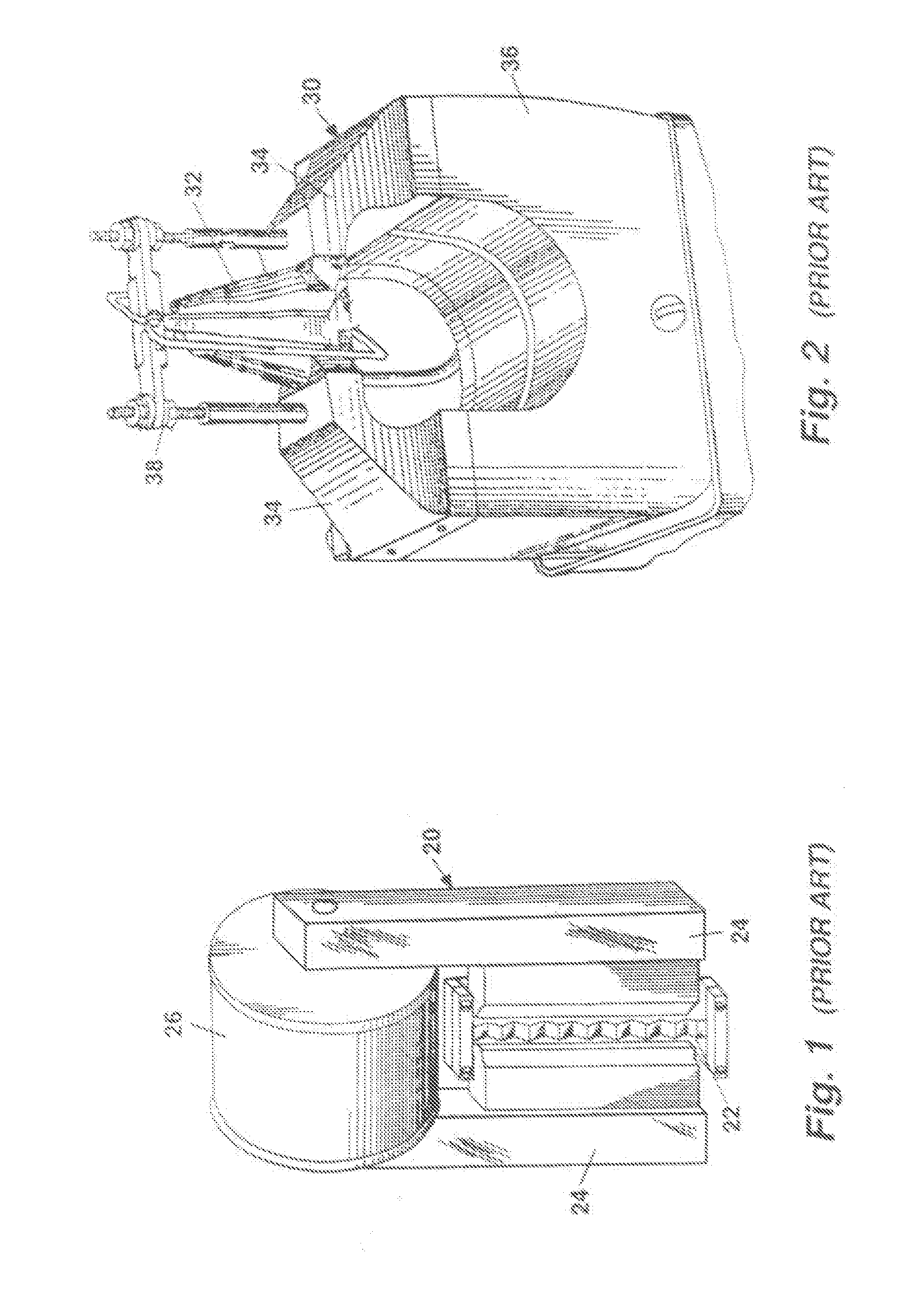
[0054]Referring now to the drawings in detail, and particularly to FIG. 1, there is represented a typical prior art ribbon microphone transducer 20, from U.S. Pat. No. 1,885,001 to Olson and incorporated herein by reference, shows a corrugated ribbon 22 suspended between ferrous poles 24 extending from an electromagnet 26. The electromagnet 26 establishes the magnetic field, which is carried through the pole pieces 24 and into proximity with the sound-responsive ribbon 22. When the ribbon 22 is vibrated by incoming sound waves, an electrical current is generated in the ribbon 22 which may then be amplified, recorded or transmitted. A typical prior art ribbon microphone transducer 30 shown in FIG. 2, as may be seen more completely in U.S. Pat. No. 3,435,143 to Fisher, incorporated herein by reference, illustrates the corrugated ribbon 32 suspended between tapered, ferrous pole pieces 34 extending from a permanent magnet 36. The tapered pole pieces 34 reduce the path length between th...


PUM

PropertyMeasurementUnit
thicknessaaaaaaaaaa
electrically conductiveaaaaaaaaaa
magnetic fieldaaaaaaaaaa

Abstract

A composite membrane acoustic transducer structure comprising a magnet assembly is arranged adjacent the composite membrane material. The magnet assembly is arranged to produce a flux field. A first layer of thin, elongate composite membrane material is held under tension. A second conductive layer is attached to the first layer of composite membrane material wherein the first and second layers of membrane material are arranged adjacent, generally parallel and offset from the magnet assembly. The assembly is arranged to produce the flux field through at least part of the first layer and the second layer.

Description

BACKGROUND OF THE INVENTION[0001]1. Field of the Invention[0002]This invention relates to acoustic transducers and more particularly to ribbon and thin film transducers and composite membranes fabricated with thin film techniques that operate at various sound wavelengths, and is based upon U.S. Provisional Application Ser. No. 60 / 620,934, filed 21 Oct. 2004, incorporated herein by reference in its entirety.[0003]2. Prior Art[0004]Designers and manufacturers of microphones used for vocal and instrument recording in studio environments look for improved ways to provide accurate sound reproduction. It would be desirable to provide characteristics to favor particular types of sounds, such as voices, grand pianos, or woodwinds as well as general designs having lower noise, higher and less distorted output, and greater consistency and longevity.[0005]Microphones generally use transducers that are configured either as the electrodynamic type, or more simply “dynamic”, and ribbon, and conde...

Claims


Application Information

Patent Timeline
Patent Type & Authority Applications(United States)
IPC IPC(8): H04R23/00
CPCH04R1/06H04R1/08H04R1/288H04R1/342H04R9/025H04R9/048Y10T29/49005H04R31/003H04R31/006H04R2307/023Y10T29/4908Y10T29/49002H04R9/08
Inventor CROWLEY, ROBERT J.
Owner SOUNDWAVE RES LAB
Learn More