Hemoglobin contrast in magneto-motive optical doppler tomography, optical coherence tomography, and ultrasound imaging methods and apparatus

a magnetomotive and contrast technology, applied in the field of medical diagnostic imaging, can solve the problems of limited axial scanning speed and spatial resolution, difficult detection of small vessels with slow flow rate, and easy to be affected by ghosting or ghost images

Inactive Publication Date: 2008-06-26
BOARD OF REGENTS THE TEXAS UNIV SYST
View PDF15 Cites 99 Cited by
  • Summary
  • Abstract
  • Description
  • Claims
  • Application Information

AI Technical Summary

Benefits of technology

[0020]The invention is a method and apparatus of imaging a blood flow, hemoglobin, and / or nanoparticles using optical coherence tomography, which comprises an externally applied temporally oscillating high-strength magnetic field with an optical tomography system to detect hemoglobin and / or nanoparticles.

Problems solved by technology

However, images obtained in EPI experiments tend to be vulnerable to an artifact known as “ghosting” or “ghost images.”
However, the sensitivity of this method is mainly dependent on the FFT time window, which limits axial scanning speed and spatial resolution when measuring slowly moving blood flow in small vessels that requires high velocity sensitivity.
Because a priori knowledge of the Doppler angle is not available, and conventional intensity OCT imaging provides a low contrast image of microvasculature structure, detecting small vessels with slow flow rates is difficult.
A disadvantage of the Wang system is that it does not provide a method to determine direction of flow within the sample and also does not provide a method for generating a two-dimensional color image of the sample indicating the flow velocity and directions within the image.
However, the paramagnetic susceptibility of human tissue is very low compared to other biocompatible agents such as ferumoxides (nanometer sized iron oxide particles).

Method used


Image

  • Hemoglobin contrast in magneto-motive optical doppler tomography, optical coherence tomography, and ultrasound imaging methods and apparatus
  • Hemoglobin contrast in magneto-motive optical doppler tomography, optical coherence tomography, and ultrasound imaging methods and apparatus
  • Hemoglobin contrast in magneto-motive optical doppler tomography, optical coherence tomography, and ultrasound imaging methods and apparatus

Examples


example 1

MM-ODT Imaging of the Doppler Shift of Hemoglobin by Applying an Oscillating Magnetic Field to a Moving Blood Sample

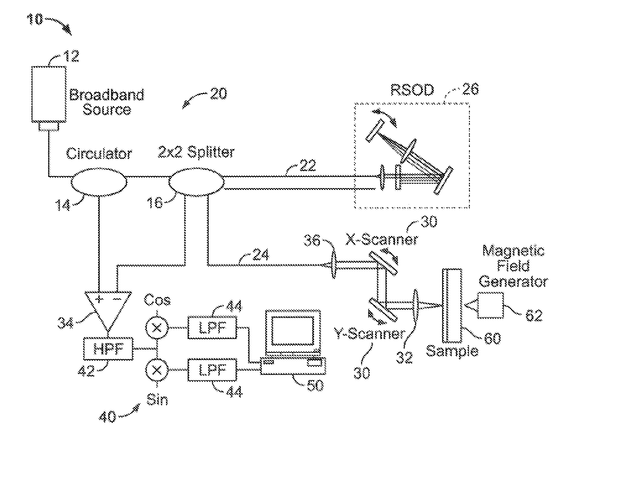
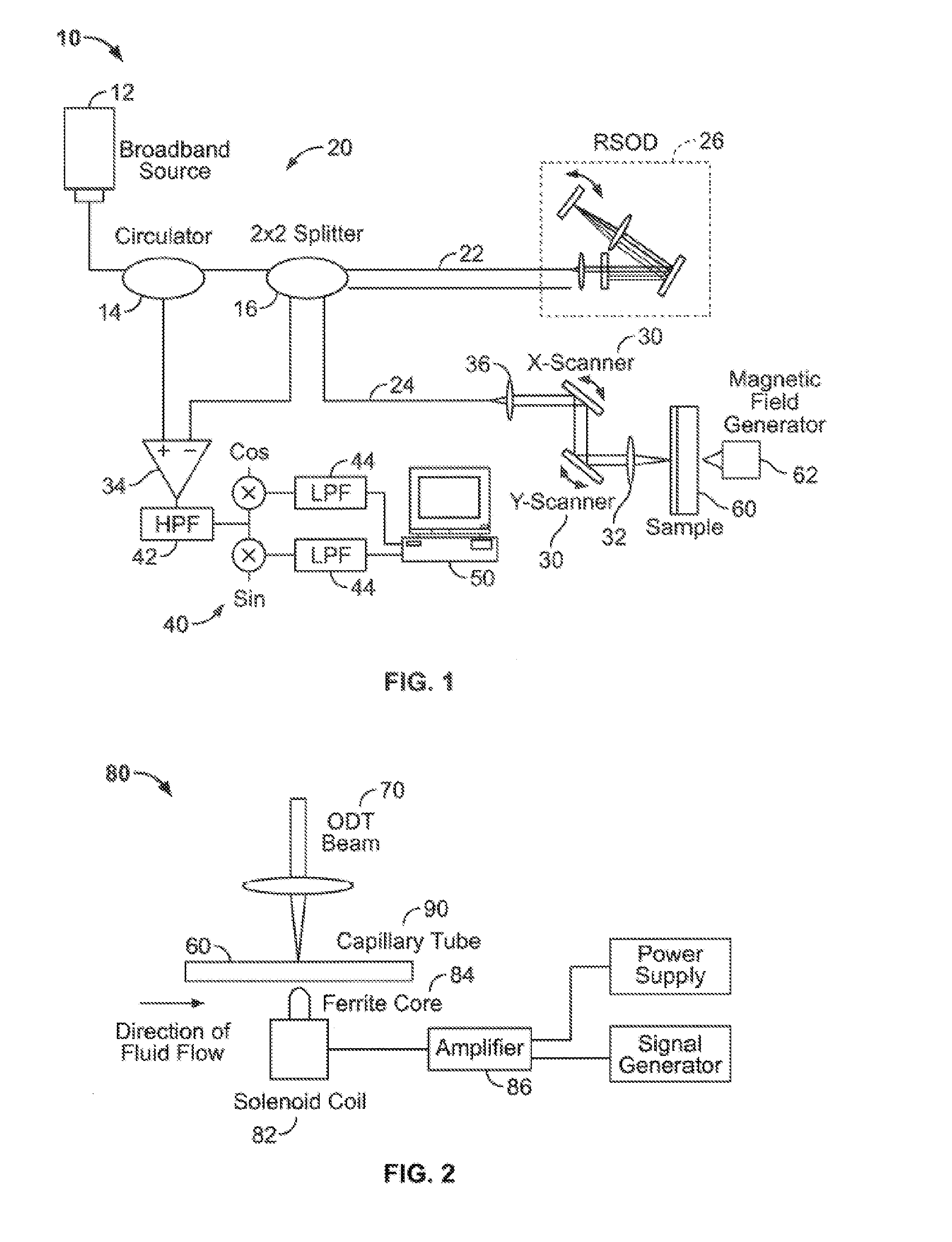
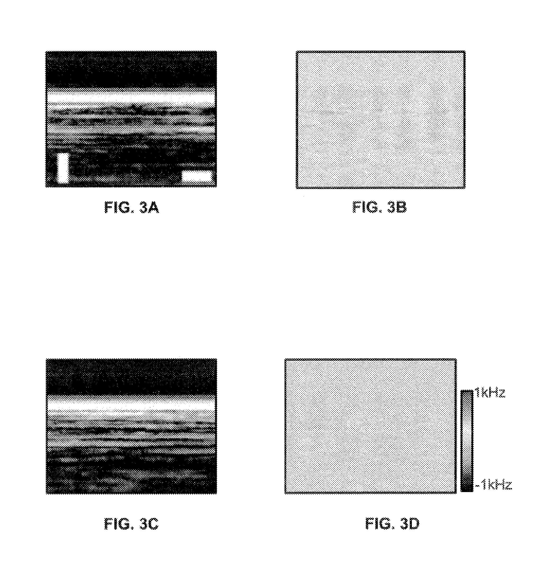
[0060]M-mode OCT / ODT images of a capillary glass tube filled with a stationary turbid solution with and without an external magnetic field as a control sample were recorded, as shown in FIGS. 3-4. A 750 μm-inner diameter glass capillary tube 200 was placed perpendicularly to the probing beam 70, as shown in FIG. 2. Fluids used for flow studies were injected through the tube at a constant flow rate controlled by a dual-syringe pump (Harvard Apparatus 11 Plus, Holliston, Mass.) with ±0.5% flow rate accuracy. The turbid solution was a mixture of deionized water and 0.5-gm latex microspheres (μs=5 mm−1). The magnetic flux density and its frequency were approximately 0.14 T and 50 Hz, respectively. M-mode OCT / ODT images were acquired for 100 ms per frame. FIGS. 3a and 3b show M-mode OCT and ODT images without any external magnetic field, respectively. The ODT image in FIG. ...

example 2

[0194]A solenoid coil with a ferrite core was used to apply a sinusoidal magnetic field to tissues taken from the liver of an ApoE− / − knockout mouse. One mouse was loaded with magnetic nanoparticles one week before imaging while an unloaded mouse served as a control. FIG. 11A shows a solenoid drive signal (top) and optical pathlength change (bottom) observed in mouse loaded with nanoparticles. FIG. 11B shows a solenoid drive signal (top) and optical pathlength change (bottom) observed in control mouse (no nanoparticles). These data demonstrate that iron oxide particles that have been ingested by macrophages in livers and spleens of the mice. Moreover, the particles have put in motion with a magnet and detected with differential phase OCT using the systems and methods described herein.

[0195]To calculate magnetic field strength a finite element method (FEM) can be used. Maxwell equations subjected to certain boundary conditions can be used to solve low-frequency magnetostatic problems...

example 3

[0210]Colloidal suspensions of SPIO nanoparticles are tissue-specific MRI contrast agents approved by the United States Food and Drug Administration (FDA) for human use in 1997. SPIO particles are also known as Ferumoxides or AMI-25 and their trade name is Feridex® I.V. (USA) and Endorem® (EU). Mean core diameter of these particles is 20 nm and total aggregation diameter is about 100 nm. SPIO nanoparticles comprise nonstoichiometric magnetite crystalline cores, iron, and dextran T-10 coating that is used to prevent aggregation and stabilization in the liver. 80% of injected dose of SPIO nanoparticles accumulate in tissue based macrophages (Kupffer cells) due to the relatively short blood half life compared to ultrasmall SPIO nanoparticles. Uptake of SPIO nanoparticles by macrophage cells is directly proportional to the intravenous injection (IV) concentration, blood half life, and core size.

[0211]To evaluate magnetic force on superparamagnetic (SPIO) nanoparticles, magnetic potentia...


PUM


Abstract

Provided herein are systems, methods, and compositions for the use of optical coherence tomography for detection of cells.

Description

CROSS-REFERENCE TO RELATED APPLICATIONS[0001]The present application is a continuation-in-part of U.S. patent application Ser. No. 11 / 550,771, filed Oct. 18, 2006, is a continuation-in part of application Ser. No. 11 / 441,824, filed May 26, 2006, which claims the benefit of U.S. Provisional Application No. 60 / 685,559, filed on May 27, 2005, and is a continuation-in-part of application Ser. No. 11 / 784,477, filed Apr. 6, 2007, which claims the benefit of U.S. Provisional Application No. 60 / 790,248, filed Apr. 7, 2006. The aforementioned applications are herein incorporated by reference in their entirety.FUNDING[0002]This invention was supported by funds from the National Institutes of Health (AR47551, EB002495 and EB002021) and the Texas Advanced Technology Program. The U.S. Government may have certain rights in the invention.BACKGROUND[0003]The present invention relates in general to the art of medical diagnostic imaging and in particular to imaging blood flow using magneto-motive opt...

Claims


Application Information

Patent Timeline
Patent Type & Authority Applications(United States)
IPC IPC(8): A61B5/05
CPCA61B5/0066A61B5/0261A61B5/0275A61B5/0515A61B5/6852A61B8/488A61B8/13G01N21/1717G01N21/4795A61B5/0035A61B5/05A61B8/06A61B5/026A61B5/725A61B2576/00A61N2/02
Inventor MILNER, THOMAS E.
Owner BOARD OF REGENTS THE TEXAS UNIV SYST
Why Eureka
Try Eureka