
Temperature control for performing heat process on resist film

Active Publication Date: 2008-07-03
TOKYO ELECTRON LTD
View PDF1 Cites 17 Cited by
  • Summary
  • Abstract
  • Description
  • Claims
  • Application Information

AI Technical Summary

Benefits of technology

[0018]In the first aspect, the method may comprise the first step arranged to use a test substrate in measuring the stepped response waveform for composing the pulsed response waveform, and then using the pulsed response waveform to acquire relation information showing a relation between the target temperatures and temperatures of the test substrate at the plurality of measurement points; the second step arranged to acquire temperature distribution information by use of measured temperatures of the test substrate, measured at the plurality of measurement points before adjustment of the target temperatures, and then determine adjustment information by use of the relation information acquired in the first step and the temperature distribution information; and the third step arranged to adjust the target temperatures by use of the adjustment information acquired in the second step. Thus, the temperatures of a substrate at the plurality of measurement points can be adjusted to a desired temperature, so that the variation in temperature at the plurality of measurement points can be decreased.
[0024]According to this constitution, the adjustment value required to eliminate the shift of the temperature can be calculated in accordance with the preset time point by use of the inverse matrix from the temperature distribution information corresponding to the shift of the temperature from a desired temperature state. Thus, when the target temperature is adjusted according to this adjustment value, the shift of the temperature of the substrate at the preset time point can be eliminated and becomes the desired temperature state.
[0027]According to this constitution, the optimal value of the adjustment value is searched for by the searching method such as the genetic algorithm. Thus, when the target temperature is adjusted by use of the adjustment value thus determined, the temperature of the substrate can be controlled so as to be a desired temperature state with high precision.
[0031]With this arrangement, the temperature stability in the operation for calculating adjustment information is improved, so that the adjustment information can be acquired with high precision.
[0041]Where the temperature controller controls to decrease a deviation between the target temperature and the detected temperature, the detected temperature may be adjusted instead of the target temperature, to provide the same effect where the target temperature is adjusted, or both of the target temperature and detected temperature may be adjusted to provide the same effect.

Problems solved by technology

However, for example, in a transient time when the semiconductor wafer is placed on the hot plate and the heat process is started, even if the temperature of the hot plate is uniformly controlled, the temperature of the semiconductor wafer is not equal to the temperature of the hot plate.
As described above, conventionally, even if the temperature of a hot plate is controlled to be in a desired state, the temperature of the semiconductor wafer can be hardly set in a desired temperature state.

Method used


Image

  • Temperature control for performing heat process on resist film
  • Temperature control for performing heat process on resist film
  • Temperature control for performing heat process on resist film

Examples


Embodiment Construction

[0089]An embodiment of the present invention will now be described with reference to the accompanying drawings.

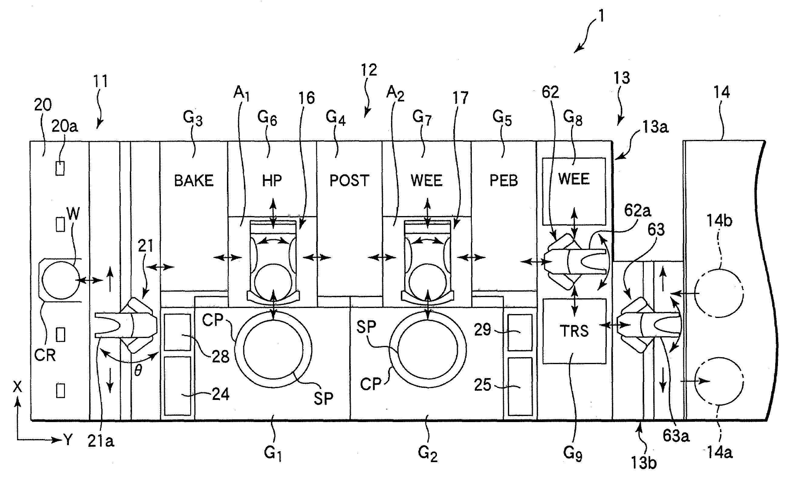
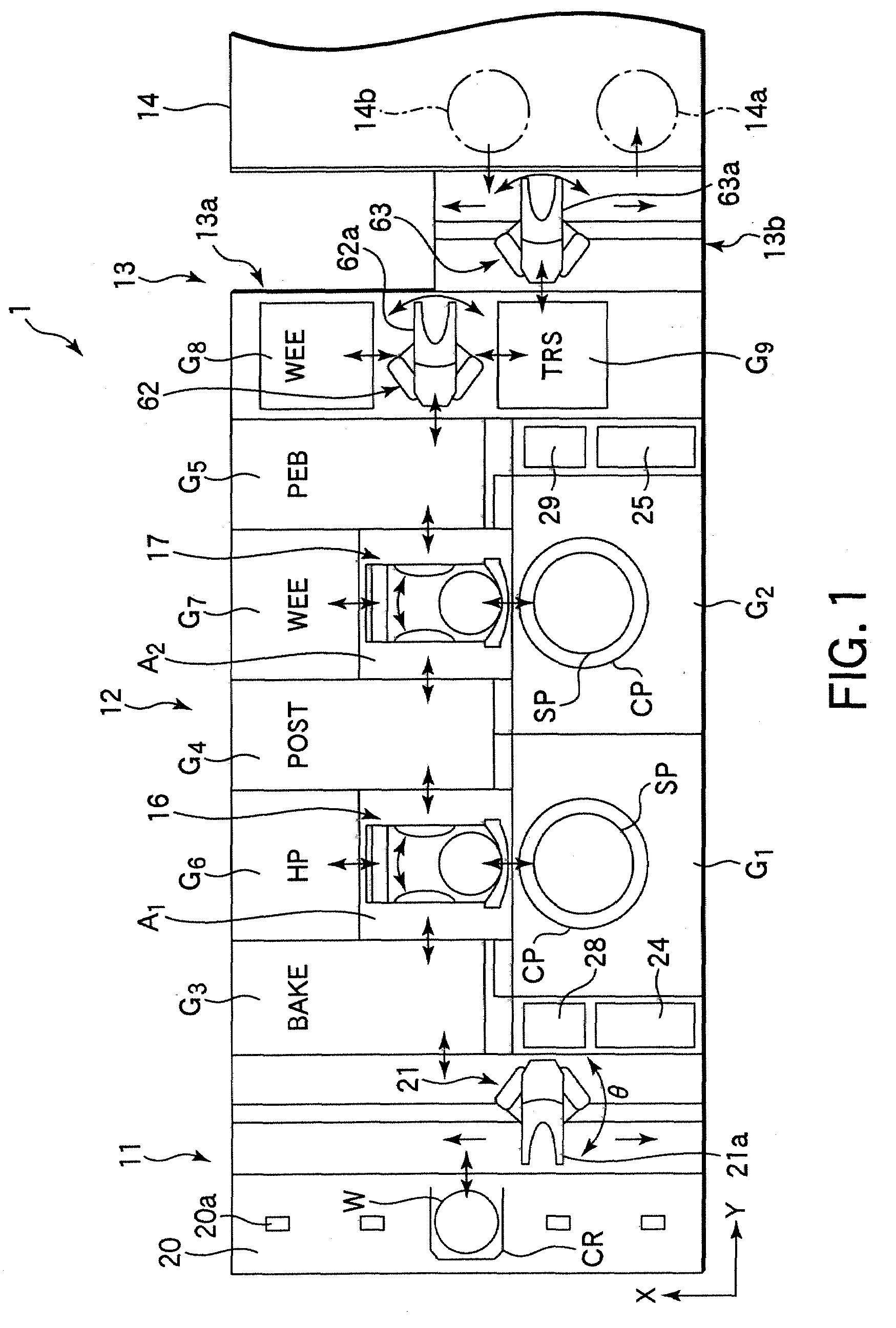
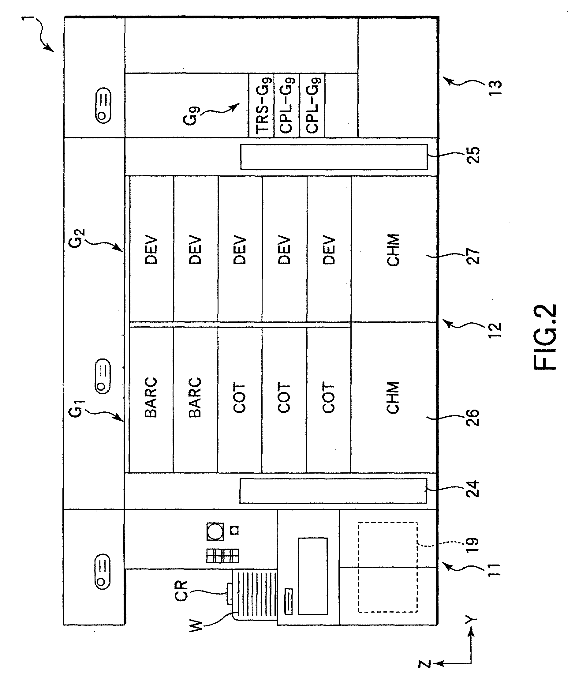
[0090]FIG. 1 is a plan view schematically showing a resist coating / developing system provided with a heat processing unit that adopts a temperature control method according to an embodiment of the present invention. FIGS. 2 and 3 are a front view and a back view, respectively, of the resist coating / developing system shown in FIG. 1.

[0091]This resist coating / developing system 1 includes a transfer station used as a cassette station 11, a process station 12 comprising a plurality of processing units, and an interface station 13 located adjacent to the process station 12 and configured to transfer wafers W between a light exposure apparatus 14 and the process station 12.

[0092]The cassette station 11 is used such that wafer cassettes (CR) are transferred thereto from other systems, wherein each of these wafer cassettes (CR) horizontally stores a plurality of wafers W to be proc...


PUM

PropertyMeasurementUnit
Temperatureaaaaaaaaaa
Timeaaaaaaaaaa
Distributionaaaaaaaaaa

Abstract

A temperature control method for a heat process on a resist film on a substrate includes first and second steps. The first step includes measuring a stepped response waveform of measured temperatures of a substrate at measurement points while changing stepwise each target temperature, then using this result to compose a pulsed response waveform with respect to a change of a pulsed target temperature, then using this result to compose a triangular response waveform with respect to a change of a triangular target temperature, and then using this result to acquire a matrix as relation information showing a relation between the target temperatures and temperatures of the substrate at measurement points. The second step includes acquiring temperature distribution information by use of measured temperatures of the substrate placed on the hot plate, measured at measurement points before adjustment of the target temperatures, and then calculating adjustment information by use of the relation information acquired in the first step and the temperature distribution information, thereby determining adjustment information.

Description

BACKGROUND OF THE INVENTION[0001]1. Field of the Invention[0002]The present invention relates to a temperature control method for controlling the temperature of a hot plate, so that respective measured temperatures of the hot plate at a plurality of measurement points conform to respective target temperatures. This method is adopted in a heat processing apparatus for performing a heat process on a substrate placed on a hot plate, which is used in a coating / developing system for applying a resist coating onto a substrate, such as a semiconductor wafer, to form a resist film and then performing development on the resist film after light exposure. The present invention further relates to an adjusting apparatus, a temperature controller, a program, a storage medium, and a heat processing apparatus, which are suitably compatible with the temperature control method. Particularly, the present invention relates to a suitable technique for suppressing a variation in temperature during a tran...

Claims


Application Information

Patent Timeline
IPC IPC(8): H01L21/00H05B3/68
CPCH01L21/67248G03F7/40H01L21/67098
Inventor OOKURA, JUNSEKIMOTO, EIICHINAKAYAMA, HISAKAZU
Owner TOKYO ELECTRON LTD
Learn More