System and Method for Improving Video Image Sharpness

Active Publication Date: 2008-07-03
TEXAS INSTR INC
View PDF10 Cites 10 Cited by
  • Summary
  • Abstract
  • Description
  • Claims
  • Application Information

AI Technical Summary

Benefits of technology

[0007]In another aspect, the invention provides a method of improving video image sharpness. In one embodiment, the method includes: (1) generating plural sub-frames from a received frame of a video image, (2) spatially filtering the plural sub-frames with respect to one another based on a display sequence thereof and (3) providing the plural sub-frames to a bit plane formatter.
[0008]In yet another aspect, the invention provides a continuous-light-emitting video display system. In one aspect, the continuous-light-emitting video display system includes: (1) a processing system configured to convert a received image signal into video frames, (2) a frame store / format module coupled to the processing system and configured to convert the video frames into bit planes, (3) a continuous-light-emitting video display coupled to the frame store / format module and (4) a sequence controller coupled to the frame store / format module and configured to deliver the bit planes to the continuous-light-emitting video display according to an order. The frame store / format module contains a system for improving video image sharpness that includes: (1) a sub-frame generator configured to receive a frame of a video image and generate plural sub-frames therefrom and (2) a spatial filter, associated with the sub-frame generator and configured to cause the plural sub-frames to be spatially filtered with respect to one another based on a display sequence thereof, the display sequence causing the plural sub-frames to be ordered in terms of increasing sharpness and a subsequent portion of the display sequence causes the plural sub-frames to be ordered in terms of decreasing sharpness.

Problems solved by technology

In continuous-light-emitting video displays, the continuous emission of light can lead to significant degradation of video image quality.
Motion of objects in the video image causes adjacent video frames to contain different images, resulting in the blurring of images, particularly at their edges.
Unfortunately, generating interpolated images requires significant computation and storage capability and thus adds substantial complexity and cost to any device having that capability.

Method used


Image

  • System and Method for Improving Video Image Sharpness
  • System and Method for Improving Video Image Sharpness
  • System and Method for Improving Video Image Sharpness

Examples


Embodiment Construction

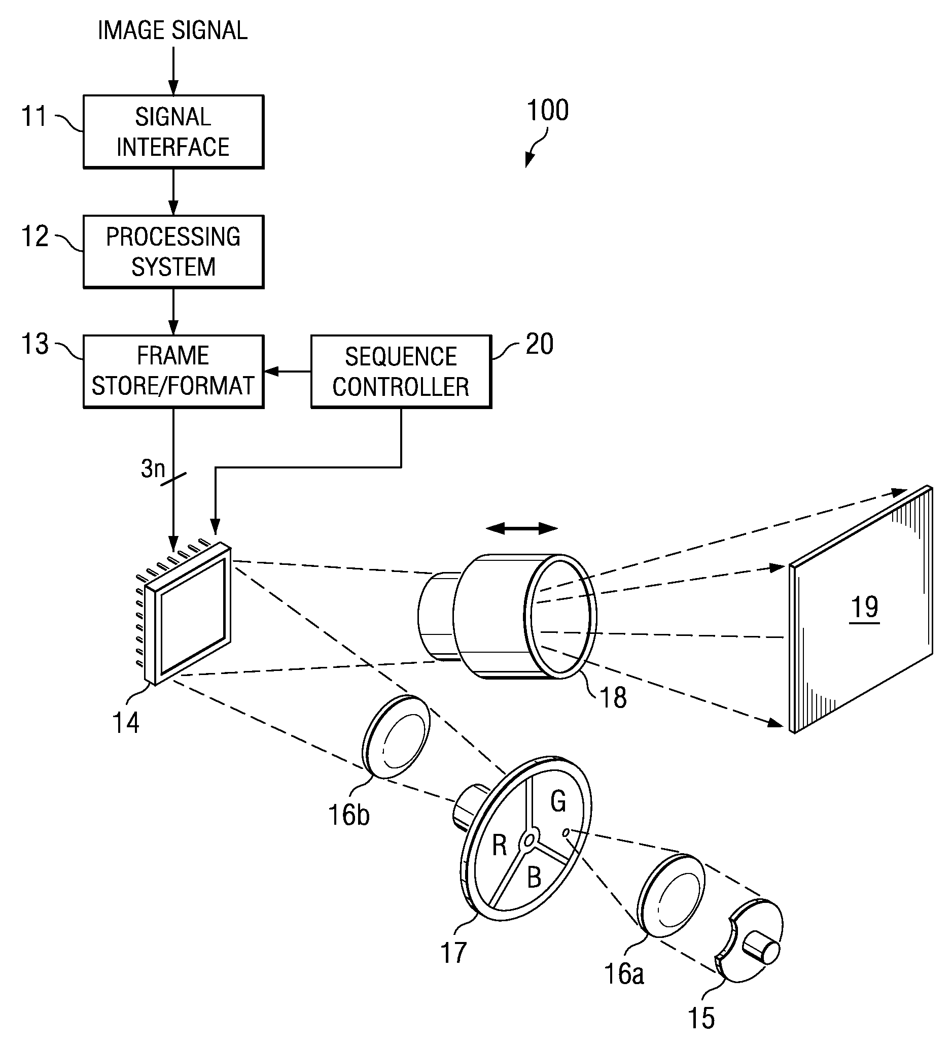
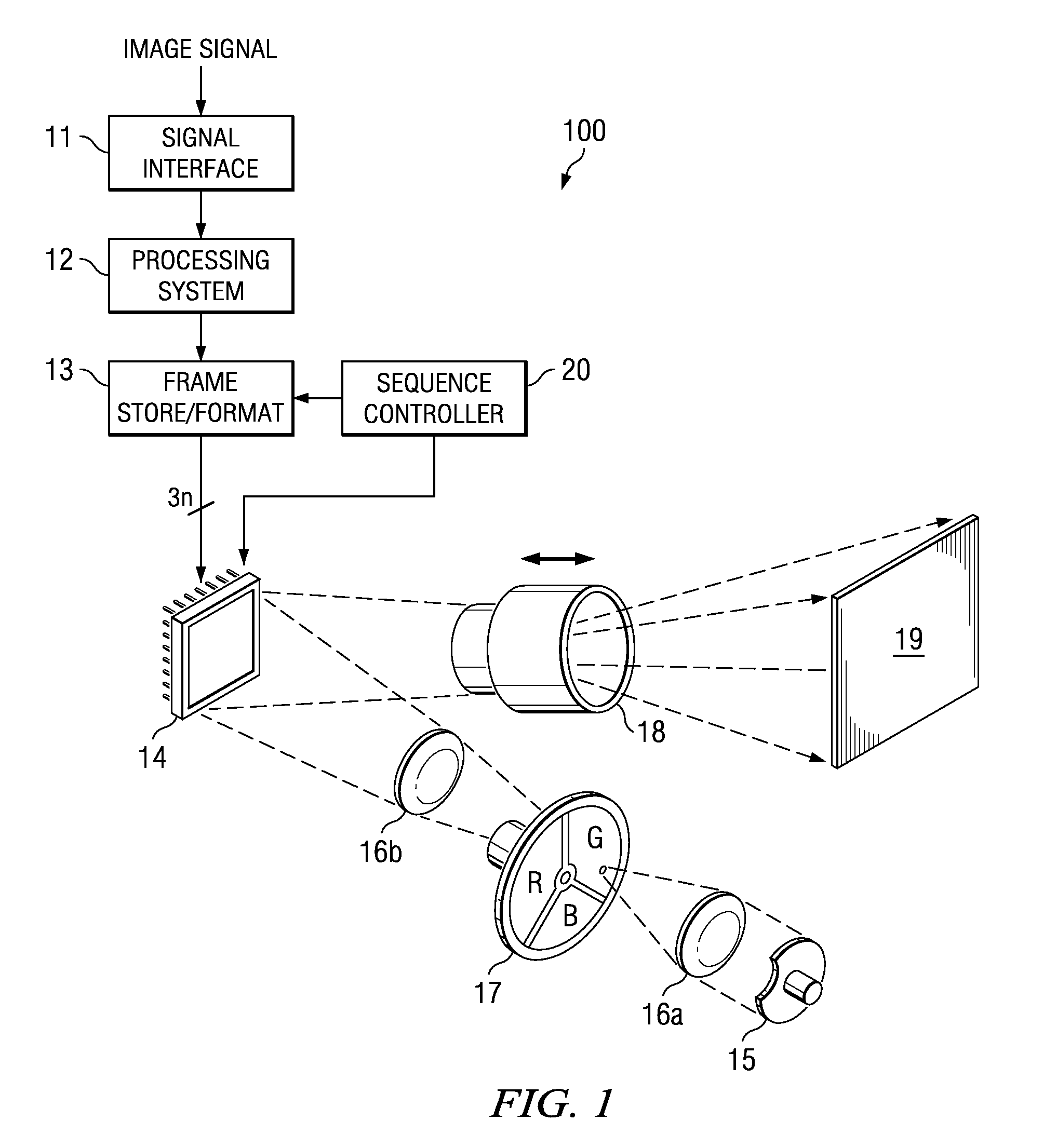
[0019]FIG. 1 illustrates one embodiment of a projection visual display system 100, which is one type of continuous-light-emitting video display and uses an SLM having a DMD 14 therein to generate real-time images from an input image signal. The input image signal may be from a television tuner, Motion Picture Experts Group (MPEG) decoder, video disc player, video cassette player, personal computer (PC) graphics card or the like. Only those components significant to main-screen pixel data processing are shown. Other components, such as might be used for processing synchronization and audio signals or secondary screen features, such as closed captioning, are not shown for simplicity's sake.

[0020]A white light source 15 shines (typically white) light through a concentrating lens 16a, a color wheel 17 and a collimating lens 16b. The light, now being colored as a function of the position of the color wheel 17, reflects off a DMD 16 and through a lens 18 to form an image on a screen 19.

[0...


PUM


Abstract

A system for, and method of, improving video image sharpness and a continuous-light-emitting video display system employing the system or the method. In one embodiment, the system for improving video image sharpness includes: (1) a sub-frame generator configured to receive a frame of a video image and generate plural sub-frames therefrom and (2) a spatial filter, associated with the sub-frame generator and configured to cause the plural sub-frames to be spatially filtered with respect to one another based on a display sequence thereof.

Description

TECHNICAL FIELD OF THE INVENTION[0001]The invention is directed, in general, to visual displays and, more particularly, to a system and method for improving video image sharpness, particularly with respect to video images to be displayed on continuous-light-emitting video displays, such as digital micro-mirror devices (DMDs).BACKGROUND OF THE INVENTION[0002]Several modern display technologies are used to display moving, or “video,” images, such as liquid-crystal displays (LCDs) (which are suitable for either front or rear projection or direct view), DMDs (which are suitable for either front or rear projection as part of a spatial light modulator, or SLM, -based projector system) or plasma displays (which are suitable only for direct view). These display technologies differ fundamentally from the traditional cathode ray tube (CRT) in that they emit light continuously while displaying a single video frame. In contrast, a CRT emits a short burst of light once per video frame with inter...

Claims


Application Information

Patent Timeline
IPC IPC(8): H04N9/77H04N5/14G09G5/02
CPCG09G3/2022G09G3/346G09G5/399H04N9/646G09G2320/0261G09G2320/0266H04N9/3111G09G2310/0235
Inventor RUSSELL, ANDREW I.
Owner TEXAS INSTR INC
Why Eureka
Try Eureka