Excepting switching transients, the ID·VDS product in the
power MOSFET remains small, and power dissipation in the switch remains low.
During such operation, these power devices lose energy to
self heating, both during periods of on-state conduction and during the act of switching.
These switching and conduction losses adversely limit the power converter's efficiency.
For
fast switching transistors operating at low voltages, however, these additional losses are small compared to the gate drive and conduction losses in the converter.
Bigger MOSFETs exhibit lower on-resistance and less conductive loss but are harder to drive, losing efficiency especially at higher switching frequencies f.
Unfortunately, up-down
converters typically require four switches and suffer in efficiency as a result.
While transformers or coupled inductors may be used to achieve up-down regulator operation and avoid the need for more switches, in non-isolated converter applications, multi-winding inductors are unacceptably large compared to single-winding coils.
Unwanted
noise can occur during the transitions associated with BBM operation.
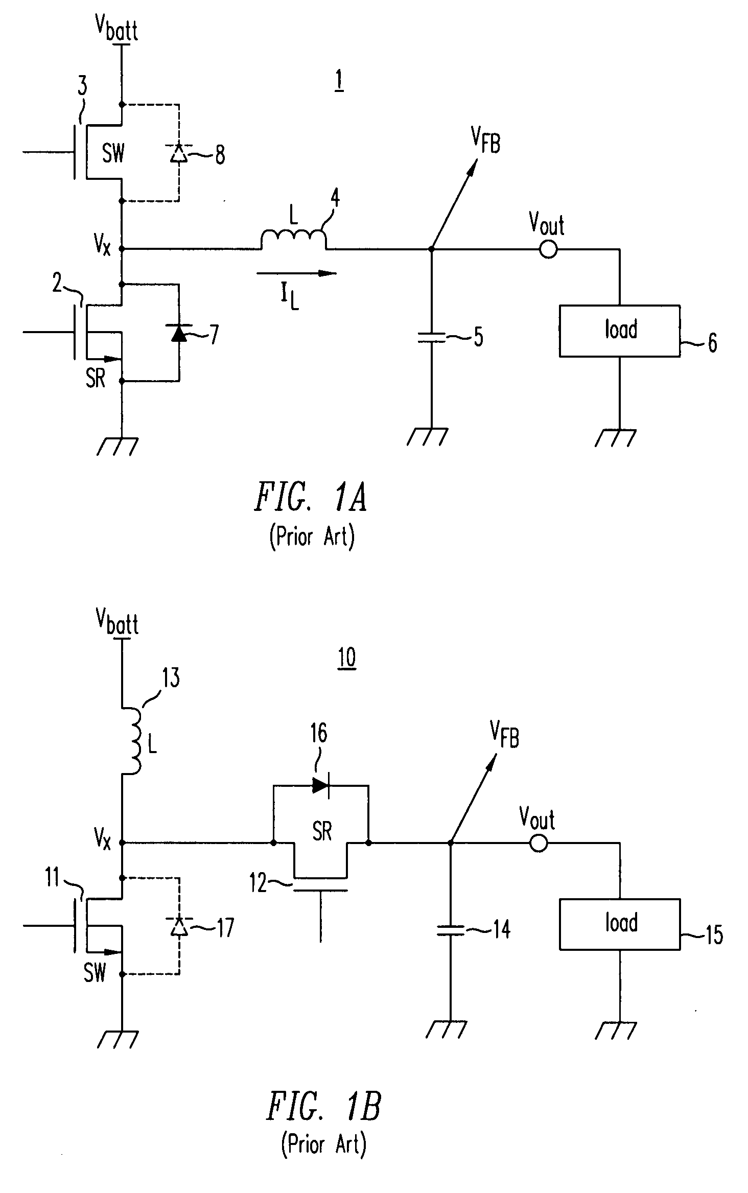
Notice that a
Buck converter cannot smoothly reach a zero or unity transfer characteristic without exhibiting some discontinuity at the extremes of D. This phenomenon occurs due to switching delays in the
power MOSFET switch and its control
and gate drive circuitry.
This minimum off-time problem impacts both synchronous, and non-synchronous Buck
converters.
A similar effect limits the operation of a synchronous
boost converter near the extremes of its range.
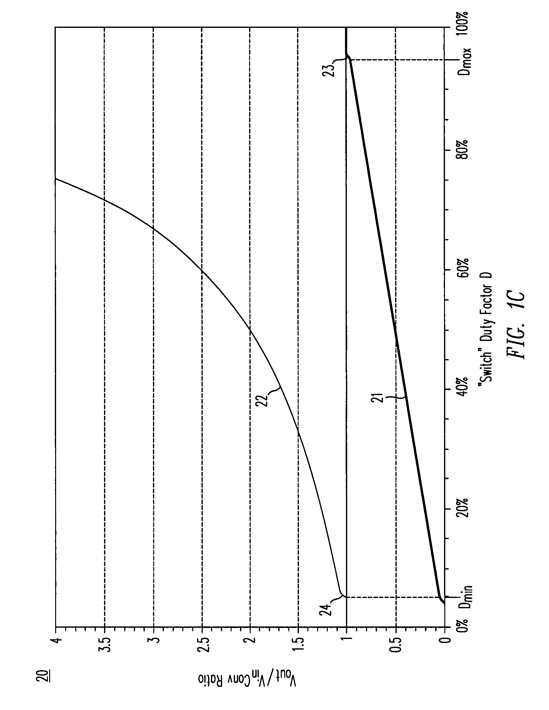
Notice that the
boost converter cannot smoothly reach a unity transfer characteristic without exhibiting some discontinuity at the extreme low end of D. This phenomenon occurs due to switching delays in the
power MOSFET switch and its control
and gate drive circuitry.
This minimum on-time problem impacts either synchronous or non-synchronous boost converters.
Moreover, at a 100% duty factor, Vout=Vin and all regulation is lost as long as the switching is halted.
The problem of non-isolated DC / DC switching converter operation near unity transfer is especially difficult in applications when the input voltage may vary above or below the desired output voltage.
Examples of this situation include the output of noisy AC adapters or circuitry which must operate by battery back-up during emergency conditions when a main source of power has failed.
Because of the limitations of Dmax, the converter cannot regulate approaching a unity conversion ratio.
Even operating at a duty factor of 92%, which is not an easy task at high frequencies, the majority of the Lilon battery's energy is wasted by using a Buck-only converter solution.
Moreover, the converter as shown requires two inductors, a characteristic highly undesirable from a user's point-of-view.
The overall loss in a Buck-boost
cascade converter is worse than the loss in a synchronous
Buck converter or a synchronous
boost converter alone, because there are more transistors in series between the input and output terminals, and because all the MOSFETs are switching all the time.
Notice also that boost mode operation efficiency (curve 108) is lower than Buck-mode operation, primarily because boost converters require higher average switch currents than Buck converters, increasing conduction losses.
So while
mode switching of a Buck-boost converter limits the loss four-switch Buck-boost operation to near unity voltage conversion ratios, the Buck-boost converter is categorically less efficient that a Buck converter or a boost converter alone.
Moreover, the fact that the converter must go through a mode transition whenever the conversion ratio is near unity can be a real problem in a number of applications, affecting transient regulation, stability and
noise.
Clearly, the Buck-boost switching regulator has many disadvantages, and especially so when operating at or near unity conversion ratios.
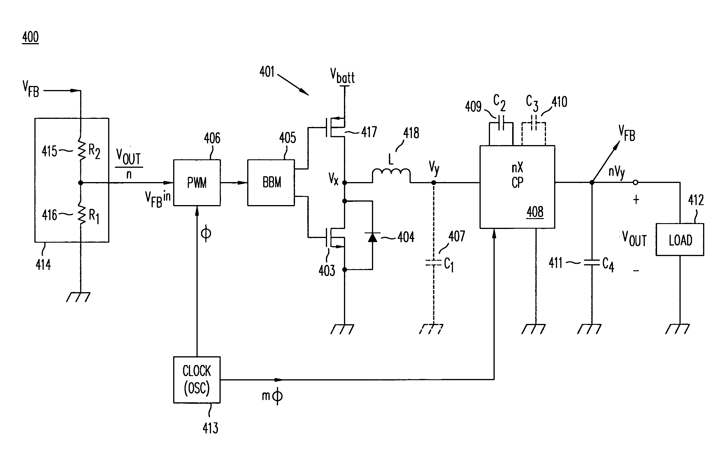
The
disadvantage is that it can only efficiently generate voltages that are exact integral multiples of the number of flying capacitors used in its
converter circuit.
A problem with
charge pump converters is they operate efficiently only at integral multiples of the number of flying capacitors; in other words, they are not voltage regulators.
Specifically, as a desired load voltage Vout drops below the voltage VCP that the
capacitor network produces, the converter cannot adapt.
The voltage-differential between the
charge pump's output voltage VCP and the regulated output voltage of the converter Vout requires a
resistor or
current source to support the voltage mismatch, and the voltage across that lossy element results in lost power and reduced efficiency.
The charge pump is not capable of delivering a voltage higher than that voltage, and a different
capacitor multiplier, i.e. a different operating mode must be employed.
Unless a load operates at an exact half-
volt integral multiple of the input voltage, however, the efficiency of the charge pump converter will suffer.
This behavior is especially problematic for battery powered products where the
battery voltage changes markedly as the
cell discharges.
Unfortunately, conditions still exist where the efficiency suffers substantially.
The mode transitions may also result in sudden current and voltage discontinuities, or produce
instability or noise.
Specifically, the charge pump converter in 1.5× mode does not perform well for conditions slightly above a unity conversion ratio, unfortunately manifesting even lower efficiencies than an inductive Buck-boost converter.
The real issue of charge pump as a power supply is that the charge pump converter is not by itself a
voltage regulator since it produces only certain fixed voltage multiples.
Examples of prior art series-pass elements include linear regulators, current sources, or resistors, all of which are lossy, i.e. dissipate power as heat and reduce the charge pump regulator's
overall efficiency.
The greater the voltage differential between the charge pump's output VCP and the desired regulated load voltage Vout (i.e. the greater the ΔV across the LDO regulator), the worse the converter's efficiency becomes.
Using a
current source instead of an LDO regulator does not improve the efficiency of the circuit.
This difference between the output of charge pump 302 (VCP) and the voltage across
filter capacitor 307 (Vout) must be supported by the conducting
current source, and therefore contributes to efficiency loss and wasted power.
As a consequence, it still dissipates power and degrades efficiency.
Eliminating the series pass device in a charge pump regulator does not improve efficiency.
So any voltage differential ΔV between a charge pump's output voltage VCP and a regulated load voltage Vout results in loss of efficiency.
Unfortunately for small ΔV, another phenomenon referred to as “dropout” can degrade the accuracy and quality of
voltage regulation.
The problem of dropout also plagues prior art switching regulators.
Whenever the input and the output voltages of a
voltage regulator approach one another within the range of several hundred millivolts, i.e. Vout≈Vin±200 mV, the quality of the converter's regulating ability suffers.
While the Buck-boost converter doesn't really exhibit permanent dropout, it can easily suffer a voltage
glitch during mode transitions whenever the converter mode switches from a Buck converter into its Buck mode into its Buck-boost mode, or when switching from Buck-boost mode to boost mode.
Unfortunately, it is well known phenomenon that all linear regulators exhibit loss of regulation, i.e. dropout, whenever ΔV across the
linear regulator's input and output terminals becomes too small.
Isolated converters such as the flyback and
forward converter are able to operate at high efficiencies near unity conversion without the need switching
modes, but their use of physically-large tapped inductors, coupled inductors, and transformers precludes their application in most portable products.
In conclusion, existing charge pump converters, Buck-boost switching regulators and other inductive switching regulators are not able to both step-up and step-down DC voltages efficiently, especially for conversion ratios near unity where Vin≈Vout.

