Unwanted
noise can occur during the transitions associated with BBM operation.
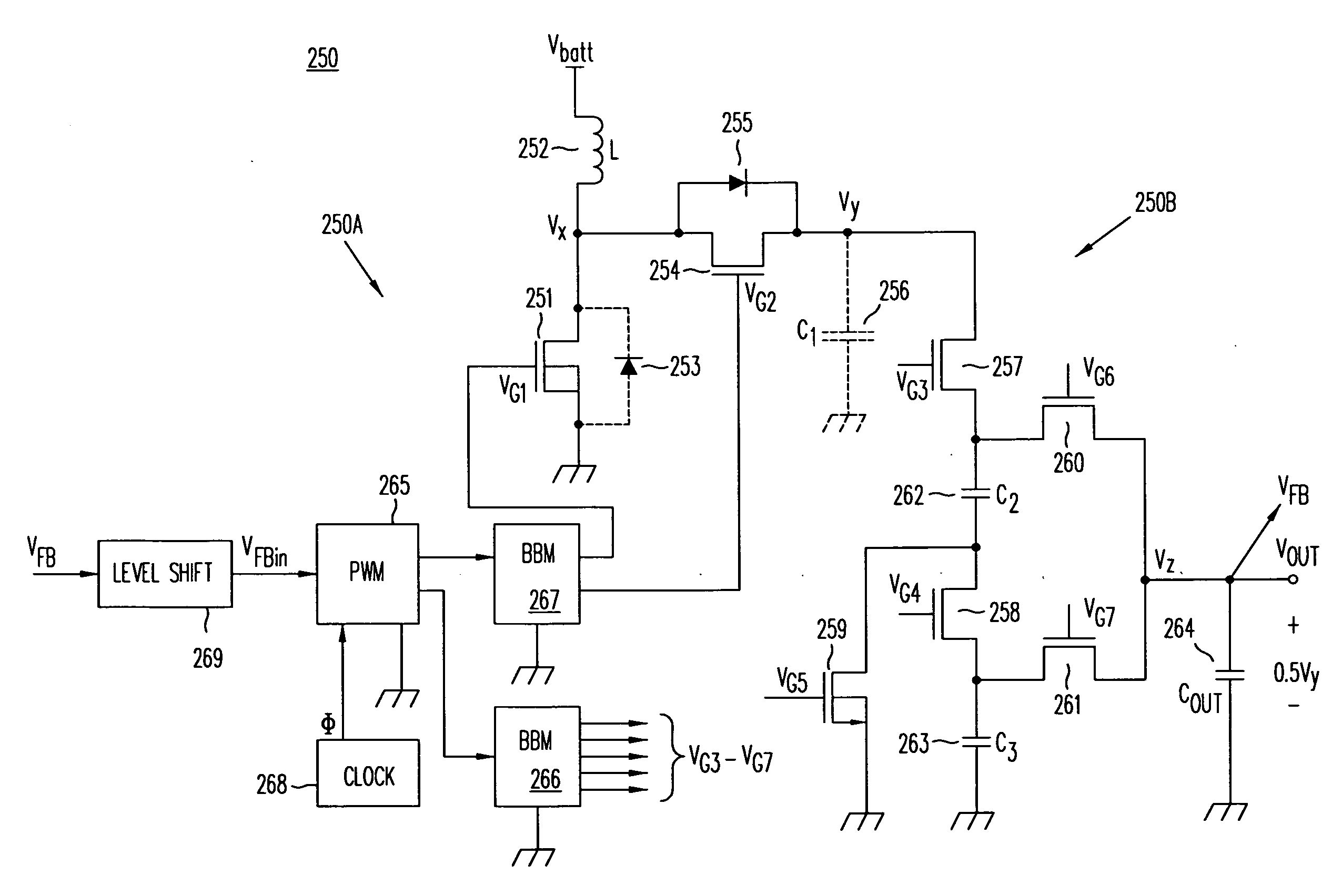
This minimum off-time problem impacts both synchronous or non-synchronous Buck
converters.
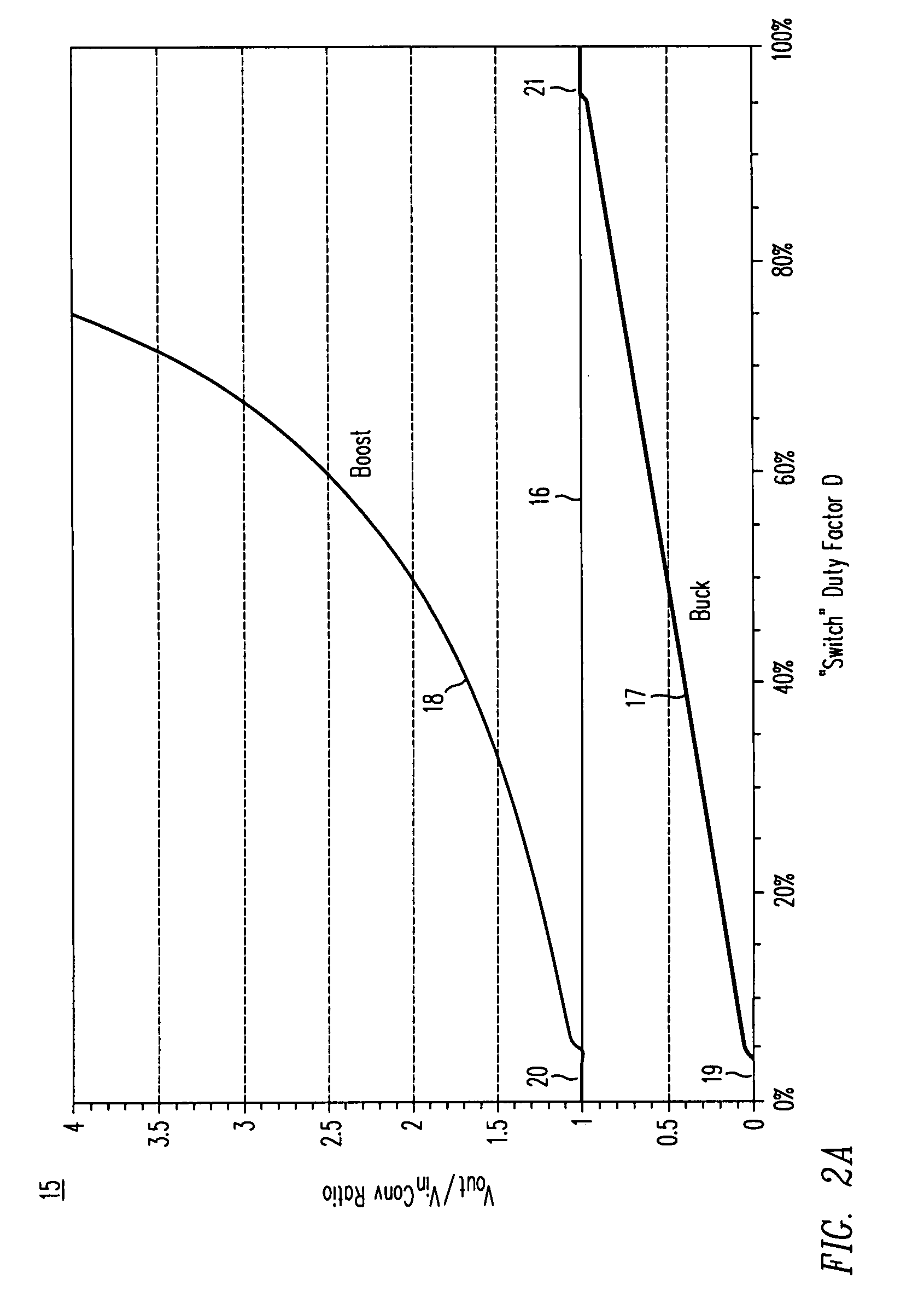
Notice that the
boost converter cannot smoothly reach a unity transfer characteristic without exhibiting some discontinuity at the extremes of D. This phenomenon occurs due to switching delays in the
power MOSFET switch and its control
and gate drive circuitry.
This minimum on time problem impacts either synchronous or non-synchronous boost
converters.
The problem of non-isolated DC / DC switching converter operation near unity transfer is especially difficult in applications when the input voltage may vary above or below the desired output voltage.
In practice, however considering battery manufacturing variations and regulator drop-out and duty factor limitations, too much battery life is sacrificed to rely on a Buck-only regulator solution.
The overall
power loss in a cascaded Buck-boost or boost-Buck
cascade is greater than the
power loss in either a synchronous Buck or synchronous
boost converter alone, because there are more transistors in series between input and output terminals, and because all the transistors are switching all the time.
Curve 85 illustrates the efficiency of Buck-boost converter 55 operating in full Buck-boost mode where all four switches are switching constantly, and as a result exhibits even greater losses and poorer efficiency than the same Buck-boost converter operating in Buck mode (curve 83).
Curve 86 illustrates the efficiency of Buck-boost converter 55 operating in full Buck-boost mode where all four switches are switching constantly, and as a result exhibits even greater losses and poorer efficiency than the same Buck-boost converter operating in boost mode (curve 84).
Thus, the efficiency penalty of using a Buck-boost converter in order to operate over a wide range of voltage conversion ratios is substantial.
The
disadvantage is that it can only efficiently generate an output voltage that is a predetermined multiple of the input voltage, based on the number of flying capacitors used in its
converter circuit.
The problem with
charge pump converters is they operate efficiently only at specific conversion multiples determined by the number of flying capacitors.
Specifically, as a desired load voltage Vout deviates from the voltage VCP that the
capacitor network produces, the
charge pump cannot adapt.
To bridge the voltage-differential between the charge pump's output voltage VCP and the desired output voltage Vout requires a
resistor or
current source, and the voltage across that lossy element results in lost power and reduced efficiency.
Unless a load operates at an exact half-
volt integral multiple of the input voltage, however, the efficiency of a charge pump converter using one or two capacitors will suffer.
This behavior is especially problematic for battery-powered products, since the
battery voltage may change markedly as the
cell discharges.
Unfortunately, conditions still exist where the efficiency suffers substantially.
The mode transitions may also result in sudden current and voltage discontinuities, or produce
instability or
noise.
Specifically, the charge pump converter in 1.5X mode does not perform well for conditions slightly above a unity conversion ratio, unfortunately manifesting efficiencies that are even lower than the efficiency of an inductive Buck-boost converter.
Whenever the input and the output voltages of a
voltage converter approach a range of several hundred milli-volts of each other, e.g. Vout≈Vin±200 mV, the quality of the converter's regulating ability suffers.
While the Buck-boost converter doesn't really exhibit permanent dropout, it can easily suffer a voltage
glitch during mode transitions whenever the converter mode switches from a
Buck converter into its Buck mode into its Buck-boost mode, or when switching from Buck-boost mode to boost mode.
As stated previously, the charge pump is incapable of regulating voltage without the use of a series connected
linear regulator to provide the regulation function.
Unfortunately, it is well known phenomenon that all linear regulators exhibit loss of regulation, i.e. dropout, whenever the ΔV across the
linear regulator's input and output terminals becomes too small.
Isolated converters such as the flyback and
forward converter are able to operate at high efficiencies near unity conversion without the need to switch
modes, but their use of physically-large tapped inductors, coupled inductors, and transformers precludes their application in most portable products.
In conclusion, no existing charge pump converter, Buck-boost switching regulator or other inductive switching regulator is able to both step-up and step-down DC voltages efficiently, especially for conversion ratios near unity where Vin≈Vout.

