
Technique for using an improved shield ring in plasma-based ion implantation

a shield ring and plasma technology, applied in vacuum evaporation coatings, chemical vapor deposition coatings, coatings, etc., can solve the problems of enlarging the area of one, inconvenient replacement process, and high cost of shield ring replacemen

Inactive Publication Date: 2008-07-03
VARIAN SEMICON EQUIP ASSOC INC
View PDF10 Cites 13 Cited by
  • Summary
  • Abstract
  • Description
  • Claims
  • Application Information

AI Technical Summary

Problems solved by technology

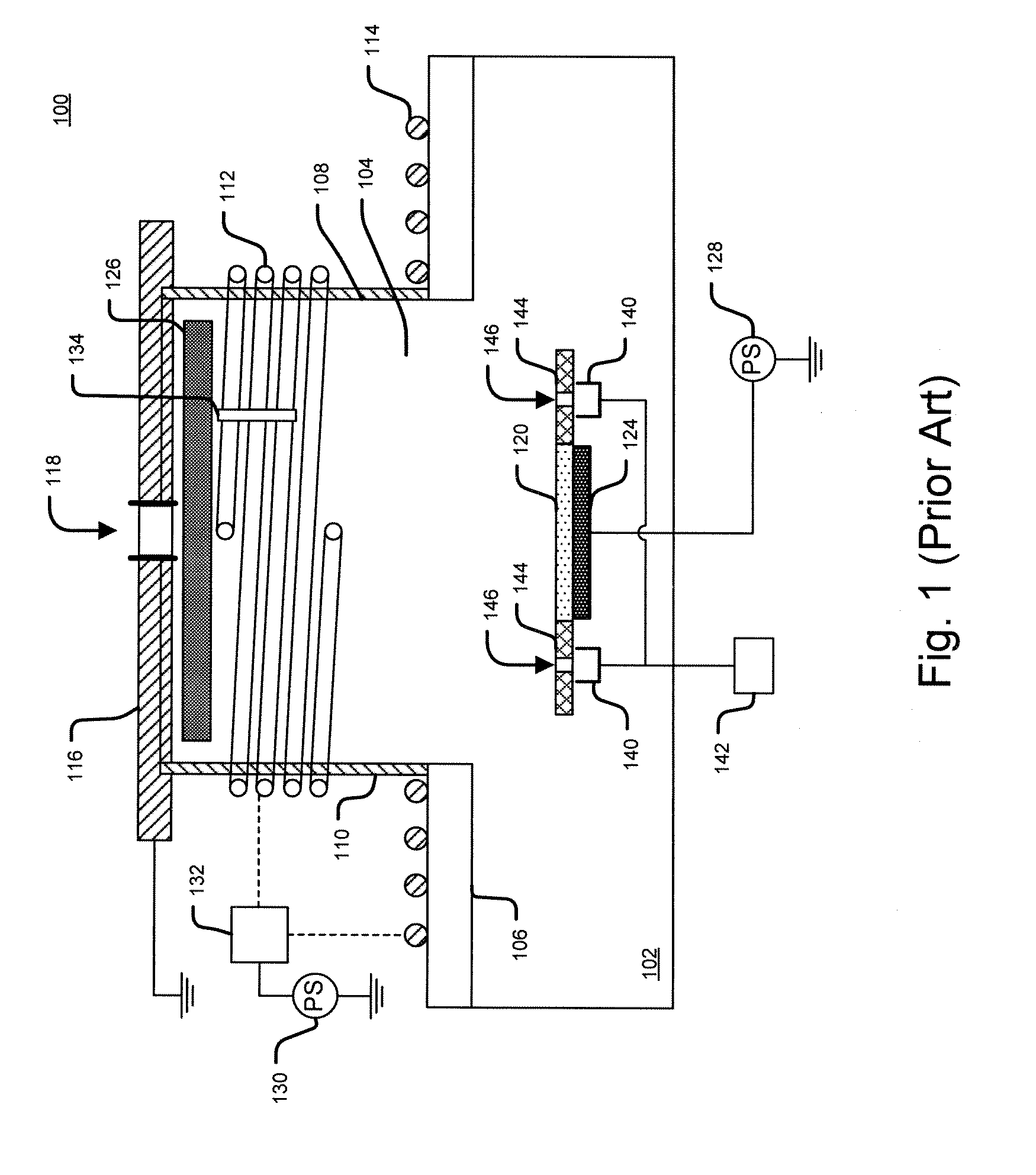
However, this often results in an undesired effect of etching the material of the shield ring 144 and, consequently, enlarging the area of the one or more shield ring apertures 146.
However, the process for replacing shield rings is often expensive, inconvenient, and tedious.

Method used


Image

  • Technique for using an improved shield ring in plasma-based ion implantation
  • Technique for using an improved shield ring in plasma-based ion implantation
  • Technique for using an improved shield ring in plasma-based ion implantation

Examples


Embodiment Construction

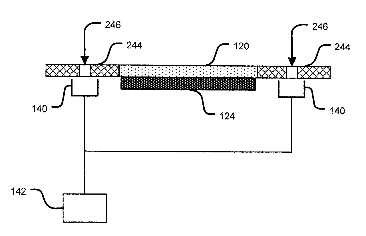
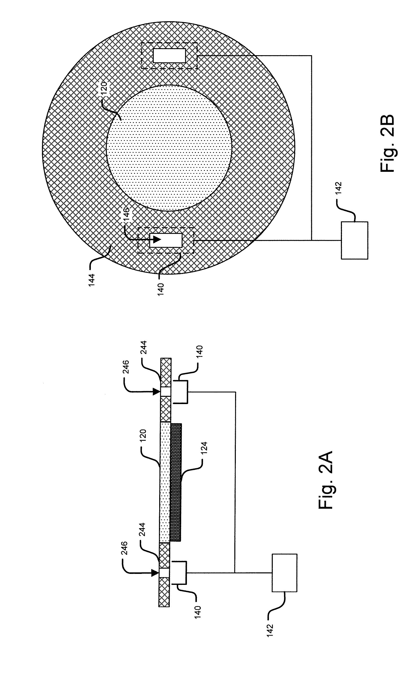
[0032]Referring to FIG. 2A, a side view of a shield ring 244 is shown in accordance with an embodiment of the present disclosure. The shield ring 244 may be in the shape of an annulus and may be positioned on a same plane as and around a periphery of the target wafer 120. The shield ring 244 may have one or more shield ring apertures 246 that define an area. One or more Faraday cups 140 may be positioned on a plane below the target wafer 120, under the one or more shield ring apertures 246 and adjacent to the platen (or E-clamp) 124. FIG. 2B depicts a top view of the shield ring 244.

[0033]In this embodiment, the area of one or more shield ring apertures 246 is smaller than the opening area of the one or more Faraday cups 140 below the ring 244. In one embodiment, the shield ring 244 may be formed of a thermally and electrically conductive material with a low etch rate, such as aluminum, and coated with silicon (Si), silicon carbide (SiC), carbon (C), graphite, or other similar low-e...


PUM

PropertyMeasurementUnit
areaaaaaaaaaaa
etch rateaaaaaaaaaa
aperture areaaaaaaaaaaa

Abstract

A technique for using an improved shield ring in plasma-based ion implantation is disclosed. In one particular exemplary embodiment, the technique may be realized as an apparatus and method for plasma-based ion implantation, such as radio frequency plasma doping (RF-PLAD). The apparatus and method may comprise a shield ring positioned on a same plane as and around a periphery of a target wafer, wherein the shield ring comprises an aperture-defining device for defining an area of at least one aperture, a Faraday cup positioned under the at least one aperture, and dose count electronics connected the Faraday cup for calculating ion dose rate. The at least one aperture may comprise at least one of a circular, arc-shaped, slit-shaped, ring-shaped, rectangular, triangular, and elliptical shape. The aperture-defining device may comprise at least one of silicon, silicon carbide, carbon, and graphite.

Description

FIELD OF THE DISCLOSURE[0001]The present disclosure relates generally to plasma-based ion implantation and, more particularly, to a technique for using an improved shield ring in plasma-based ion implantation.BACKGROUND OF THE DISCLOSURE[0002]Ion implantation is a process of depositing chemical species into a substrate by direct bombardment of the substrate with energized ions. In semiconductor fabrication, ion implanters are used primarily for doping processes that alter the type and level of conductivity of target materials. A precise doping profile in an integrated circuit (IC) substrate and its thin-film structure is often crucial for proper IC performance. To achieve a desired doping profile, one or more ion species may be implanted in different doses and at different energy levels. A specification of the ion species, doses, and energies is referred to as an ion implantation recipe.[0003]In conventional ion implantation, ions are extracted from a plasma source and are typically...

Claims


Application Information

Patent Timeline
Patent Type & Authority Applications(United States)
IPC IPC(8): C23C14/02B05C11/00
CPCH01J37/32018H01J37/32082H01J37/32412H01J37/3299H01J37/32642H01J37/32935H01J37/32422C23C14/48H01L21/265
Inventor MILLER, TIMOTHYWINDER, EDMUND J.HETEL, RICHARD J.PERSING, HAROLD M.SINGH, VIKRAM
Owner VARIAN SEMICON EQUIP ASSOC INC
Learn More