
Method for restoring or regenerating an article

a technology of article and regenerated parts, which is applied in the direction of machines/engines, mechanical equipment, superimposed coating processes, etc., can solve the problems of high temperature durability of engine components that must correspondingly increase, alloys alone are often inadequate to form turbine components located in certain locations, and coatings will typically require removal and repair

Inactive Publication Date: 2008-07-03
GENERAL ELECTRIC CO
View PDF11 Cites 6 Cited by
  • Summary
  • Abstract
  • Description
  • Claims
  • Application Information

AI Technical Summary

Problems solved by technology

However, as operating temperatures increase, the high temperature durability of the components of the engine must correspondingly increase.
While significant advantages in high temperature capabilities have been achieved through formulation of nickel and cobalt-base superalloys, such alloys alone are often inadequate to form turbine components located in certain sections of a gas turbine engine.
Although significant advances have been made in improving the durability of thermal barrier coatings, as well as diffusion coatings used for environmental protection, such coatings will typically require removal and repair under certain circumstances.
For example, thermal barrier coatings, as well as diffusion coatings, can be susceptible to various types of damage, including objects ingested by the engine, erosion, oxidation, and environmental attack.
Also, during operation of the gas turbine engine, the diffusion zone can increase in thickness, consuming even more of the underlying metal substrate.
Repeated repair / recoat processes are associated with subsequent material loss.
Additionally, component areas may be worn down by erosion or environmental attack during engine operation.
The material loss due to field service and repair processing may result in the component being under minimum wall thickness, causing the component to be scrapped.

Method used


Image

  • Method for restoring or regenerating an article
  • Method for restoring or regenerating an article
  • Method for restoring or regenerating an article

Examples


examples

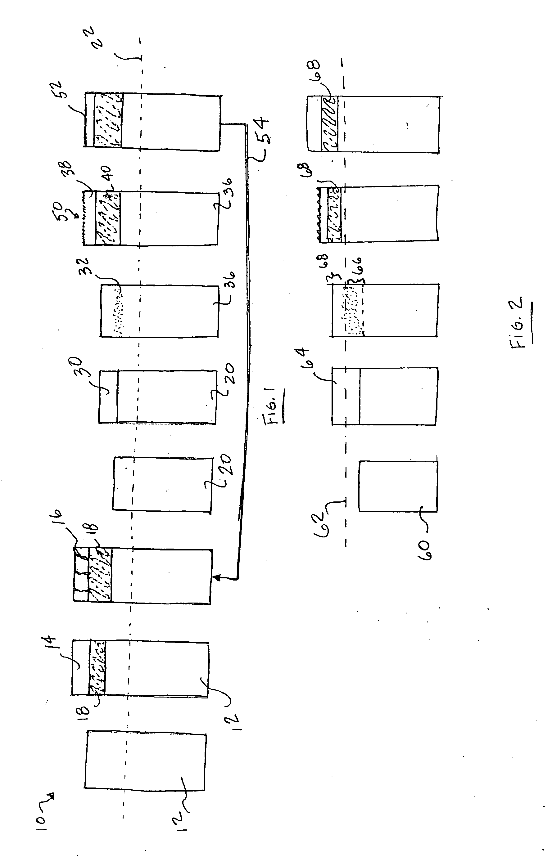
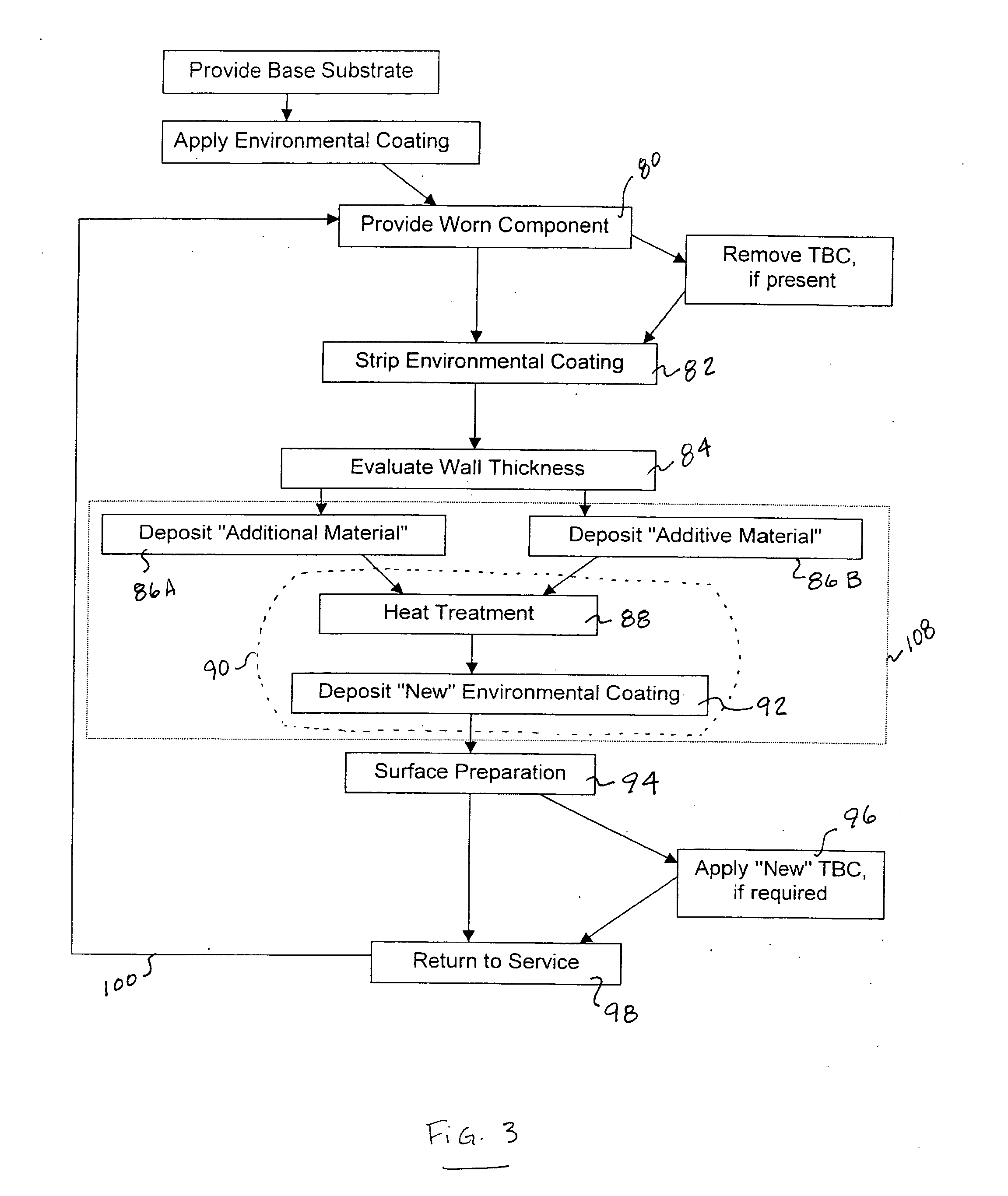
[0045]A button (substrate) comprising Rene N′5 superalloy is provided. A layer of additional Rene N′5 superalloy is deposited onto the substrate via a cathodic arc deposition process. A diffusion coating of aluminum is applied to the layer of additional Rene N′5 superalloy by ionic plasma deposition. The coated button is subjected to a heat treatment process (1975° F. (1079° C.) for 4 hours) followed by surface treatment.

[0046]A layer of additional R′142 superalloy is applied via ionic plasma deposition to a test button. The button plus additional material is subjected to a heat treatment process. Following the heat treatment process, an aluminide diffusion coating is deposited in a vapor phase deposition process.

[0047]A N′5 superalloy button has additional N′5 superalloy deposited thereon by an ion plasma deposition process. An aluminide diffusion coating is deposited via a vapor phase deposition process.

[0048]The examples show promising results in providing integral bonding betwee...


PUM

PropertyMeasurementUnit
Temperatureaaaaaaaaaa
Timeaaaaaaaaaa

Abstract

A method for restoring or regenerating an article, particularly a component for use in a gas turbine engine, includes providing a residual substrate comprised of a first material, evaluating a wall thickness of the residual substrate, and depositing a layer of a second material overlying at least a portion of the residual substrate. The second material is substantially similar in composition to the first material. The layer is deposited by vapor phase deposition, ion plasma deposition, cathodic arc deposition, sputtering, and combinations thereof. An environmental coating is deposited onto the component by vapor phase deposition, cathodic arc deposition, and combinations thereof. The method may include a heat treatment at temperatures between about 1500° F. to about 2300° F. (about 816° C. to about 1260° C.) for between about 2 to about 24 hours. The method may include a surface treatment such as grit blast polishing. Following use of the restored / regenerated component, the repair process may be repeated. At least a non-structural portion of the deposited layer may be removed during a subsequent repair. A load-bearing portion of the deposited layer, if present, may be retained on the residual substrate during a subsequent repair.

Description

BACKGROUND OF THE INVENTION[0001]This invention relates generally to restored or regenerated articles, particularly gas turbine engine components.[0002]Higher operating temperatures of gas turbine engines are continuously sought in order to increase their efficiency. However, as operating temperatures increase, the high temperature durability of the components of the engine must correspondingly increase. While significant advantages in high temperature capabilities have been achieved through formulation of nickel and cobalt-base superalloys, such alloys alone are often inadequate to form turbine components located in certain sections of a gas turbine engine. A common solution is to thermally insulate such components (e.g., turbine blades, vanes) in order to reduce their service temperatures. For this purpose, thermal barrier coatings have been applied over the metal substrate of turbine components exposed to high surface temperatures.[0003]Thermal barrier coatings typically comprise...

Claims


Application Information

Patent Timeline
IPC IPC(8): B01J19/08
CPCB23P6/007C23C4/06C23C4/185C23C14/16F05D2230/80C23C14/5893C23C28/02F01D5/005C23C14/5806
Inventor MALY, MICHAEL PATRICKCARTER, WILLIAM THOMASKELLY, THOMAS JOSEPHVELIZ, MARK DAVID
Owner GENERAL ELECTRIC CO
Learn More