Hermetic cell and method for producing same

a technology of hermetic cells and weld strength, which is applied in the direction of sustainable manufacturing/processing, envelope/bag making machinery, paper/cardboard containers, etc., can solve the problems of early degradation of laser equipment, adversely affecting the performance of degraded cells, and sputtering, so as to improve the weld strength and welding high strength, the effect of large thermal damage to the power generating elements

Inactive Publication Date: 2008-07-03
SANYO ELECTRIC CO LTD
View PDF2 Cites 3 Cited by
  • Summary
  • Abstract
  • Description
  • Claims
  • Application Information

AI Technical Summary

Benefits of technology

[0011]The present invention has been accomplished in view of the above inconveniences, and it is an object of the present invention to provide a hermetic cell excellent in weld strength and a method for producing the cell.
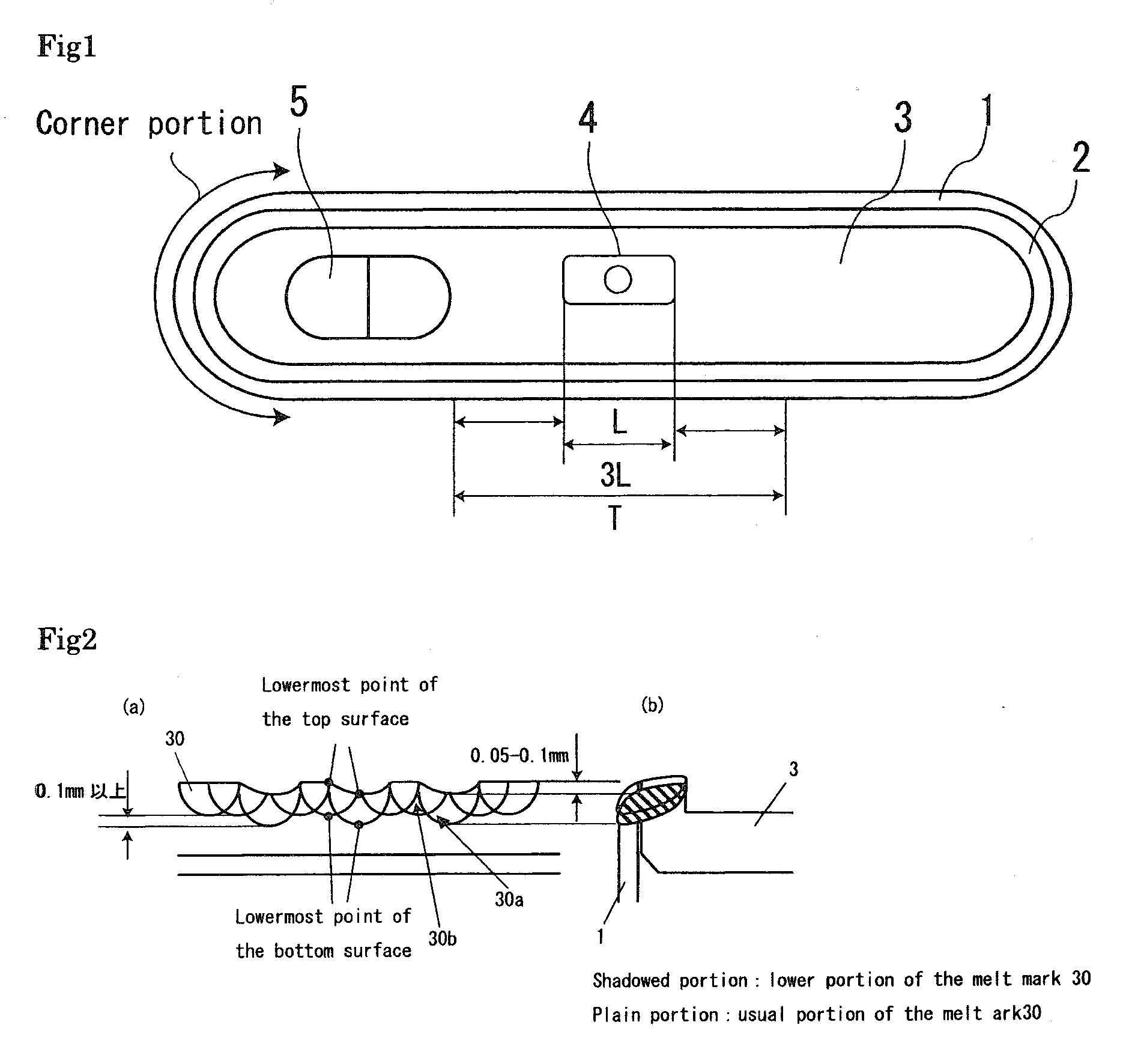
[0013]With the above-described configuration, a part of the melt mark is positioned lower in the direction of the bottom of the can than an adjacent part of the melt mark, which means that at the lower part of the melt mark the welding is carried out to a deep level. Thus, on application of external force, propagation of the force becomes discontinuous at this position to inhibit overall deformation of the welded portion, thereby significantly improving the weld strength.
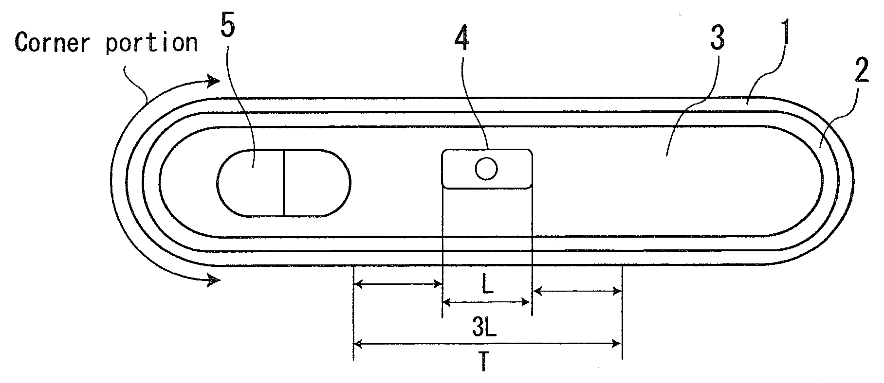
[0019]The corner portion of a cell using a rectangular can is liable to collective force, and at the terminal lateral portion (T) of the seal, a resin member for holding the terminal is thermally influenced. Therefore, enhancing the weld strength by increasing the laser output at these portions is difficult in many cases. This causes a tendency toward degraded weld strength at these portions. If welding is carried to a deep level at these portions, the weld strength is drastically enhanced. The lower portion of the melt mark may be formed not only on the corner portion and the terminal lateral portion, but also on the overall engagement portion of the can and the seal.
[0024]With these configurations, when the engagement portion is irradiated with high energy beam (e.g., laser), the portion provided with the dent portion and / or dent groove obtains thermal melting to a deeper level (to a lower position in the direction of the bottom of the can) than other portions. Thus, forming a dent portion and / or dent groove on a portion in need of large weld strength enables it to enhance the weld strength of that portion by using high energy beam of uniform strength. Thus, with these configurations, a hermetic cell having necessary and sufficient weld strength can be produced without unnecessary thermal damage to the power generating elements and other constituents.

Problems solved by technology

If the weld strength is not sufficient, cracking may occur on the melt mark when the cell is dropped, which causes leakage of the electrolytic solution and infiltration of oxygen or moisture into the cell, thus adversely affecting degraded cell performance.
However, this poses the problems of occurrence of sputtering and early degradation of the laser apparatus.
This inhibits degradation of the sealing performance of the laser welded portion.

Method used


Image

  • Hermetic cell and method for producing same
  • Hermetic cell and method for producing same
  • Hermetic cell and method for producing same

Examples


experiment 1

Measurement of Strength of the Negative Electrode Terminal Against Lateral Pressing

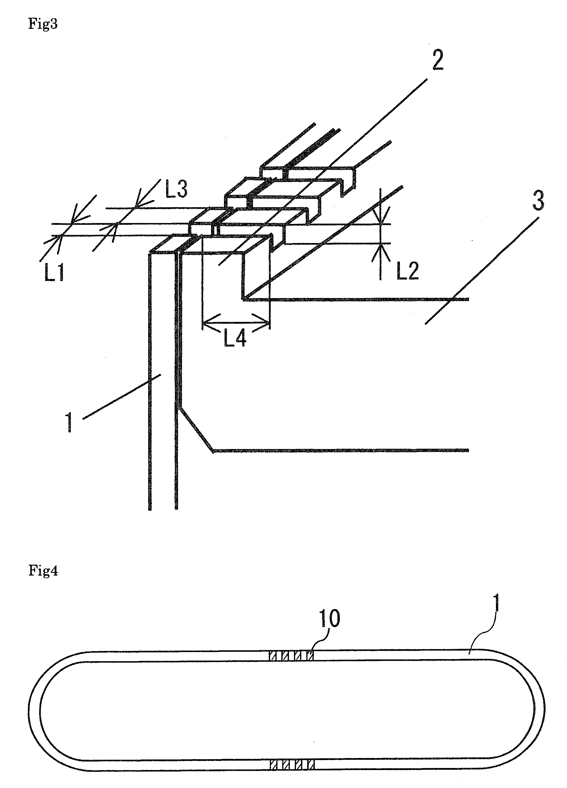
[0043]As shown in FIG. 4, on the upper end of the opening of the can having a 10 mm terminal lateral portion T, dent portions 10 dented axially inwardly were formed. The width L1 of each of the dent portions 10 shown in FIG. 3 is 0.2 mm, the depth L2 is 0.1 mm, and the distance L3 between the dent portions 10 is 1.0 mm. The seal 3 was engaged with the can 1 having the dent portions 10 so that the periphery of the outer surface of the seal and the upper end of the opening of the can would be on the same plane. Then, the portion of engagement was welded with laser, thus preparing five dummy cells 1. While each of the dummy cells 1 housed an electrode assembly composed of the positive and negative electrodes and the separator, no electrolytic solution was contained in each cell. Also, no processing was made to the periphery portion (flange) 2 of the seal 3.

[0044]As shown in FIG. 5, on the periphery of th...

experiment 2

Measurement of Strength Against Pressing on the Corner Portion

[0050]As shown in FIG. 7(a), on the upper end of the opening of the can, dent portions dented axially inwardly were formed, and dent grooves were formed on the periphery of the outer surface of the seal. For each of the dent portions and the dent grooves, the width L1 shown in FIG. 3 is 0.2 mm, the depth L2 is 0.1 mm, and the distance L3 between the dent portions and between the dent grooves is 1.0 mm. The seal was engaged with the opening of the can so that the outer surface of the sealing plate and the upper end of the opening of the can would be on the same plane. Then, the portion of engagement was welded with laser, thus preparing three dummy cells 3 each having a thickness of 65 mm, a width of 34 mm, and a height of 50 mm. While each of the dummy cells 3 housed an electrode assembly composed of the positive and negative electrodes and the separator, no electrolytic solution was contained in each cell.

[0051]For compa...

experiment 3

Dropping Test

[0054]As shown in FIG. 8, over a 10 mm range of each of the terminal lateral portions, dent portions dented axially inwardly were formed on the upper end of the opening of the can, and dent grooves were formed on the periphery of the outer surface of the seal. For each of the dent portions and the dent grooves, the width L1 shown in FIG. 3 is 0.2 mm, the depth L2 is 0.1 mm, and the distance L3 between the dent portions and between the dent grooves is 1.0 mm. The seal was engaged with the opening of the can so that the outer surface of the sealing plate and the upper end of the opening of the can would be on the same plane. Then, the portion of engagement was welded with laser, thus preparing five dummy cells 4 each having a thickness of 55 mm, a width of 34 mm, and a height of 50 mm. While each of the dummy cells 4 housed an electrode assembly composed of the positive and negative electrodes and the separator, no electrolytic solution was contained in each cell.

[0055]Fo...


PUM

PropertyMeasurementUnit
widths L1aaaaaaaaaa
depths L2aaaaaaaaaa
distance L3aaaaaaaaaa

Abstract

A hermetic cell excellent in weld strength is provided. The hermetic cell includes an can having an opening and a seal for sealing the opening of the can. A portion of engagement of the seal with the opening of the can is welded with a high energy beam, thereby hermetically sealing the can. At least one portion of a melt mark resulting from the high energy beam welding has a top surface having a lowermost point lower in a direction of a bottom of the can than a lowermost point of a top surface of an adjacent portion of the melt mark. The at least one portion of the melt mark has a bottom surface having a lowermost point lower in the direction of the bottom of the can than an lowermost point of a bottom surface of the adjacent portion of the melt mark.

Description

BACKGROUND OF THE INVENTION[0001]1) Field of the Invention[0002]The present invention relates to technology for enhancement of the weld strength of hermetic cells.[0003]2) Description of the Related Art[0004]Rectangular hermetic cells are easy to mount inside electronic appliances and thus used for power sources therefor.[0005]These hermetic cells are prepared by engaging a top plate assembly with an opening portion of the can and laser welding the portion of engagement in a hermetic manner. If the weld strength is not sufficient, cracking may occur on the melt mark when the cell is dropped, which causes leakage of the electrolytic solution and infiltration of oxygen or moisture into the cell, thus adversely affecting degraded cell performance.[0006]A possible solution to this problem is to increase the laser strength to enlarge the depth of melting of the melt mark caused by the laser, thereby enhancing the weld strength by enlarging. However, this poses the problems of occurrence ...

Claims


Application Information

Patent Timeline
Patent Type & Authority Applications(United States)
IPC IPC(8): B23K26/20B29D22/00B23K26/21H01M2/02
CPCB23K26/28B23K2201/125B29D22/003H01M2/0217H01M2/022Y10T428/13H01M2/046H01M2/0473H01M10/0436Y10T29/4911H01M2/0426B23K2101/125Y02E60/10H01M50/103H01M50/107H01M50/169H01M50/152H01M50/15Y02P70/50
Inventor YOSHIDA, SATOSHIYAMANAKA, TOMOKAZU
Owner SANYO ELECTRIC CO LTD
Why Eureka
Try Eureka