Embedded heat exchanger for heating, ventilatiion, and air conditioning (HVAC) systems and methods

a heat exchanger and heat exchanger technology, applied in the field of integrated heating, ventilation and air conditioning (hvac) systems and methods, can solve the problem that ancillary components cannot be attached to piping structures or coils, and achieve the effect of cost-effectiveness

Active Publication Date: 2008-07-10
KARAMANOS JOHN C
View PDF89 Cites 83 Cited by
  • Summary
  • Abstract
  • Description
  • Claims
  • Application Information

AI Technical Summary

Benefits of technology

[0021]Embodiments of the present invention allow such ancillary components to be attached with piping structures in a factory setting, prior to shipment to the installation site. Accordingly, these enhanced and improved techniques are well suited for protecting ancillary HVAC system components from damage when they are attached with a piping structure during transport. These protective features avoid the situation where a mechanical contractor be compelled to charge a manufacturer due to damage incurred during shipping. Moreover, these techniques are very cost effective, as

Problems solved by technology

Relatedly, in many current methods, an ancillary component cannot be attached with a piping structu

Method used


Image

  • Embedded heat exchanger for heating, ventilatiion, and air conditioning (HVAC) systems and methods
  • Embedded heat exchanger for heating, ventilatiion, and air conditioning (HVAC) systems and methods
  • Embedded heat exchanger for heating, ventilatiion, and air conditioning (HVAC) systems and methods

Examples


Embodiment Construction

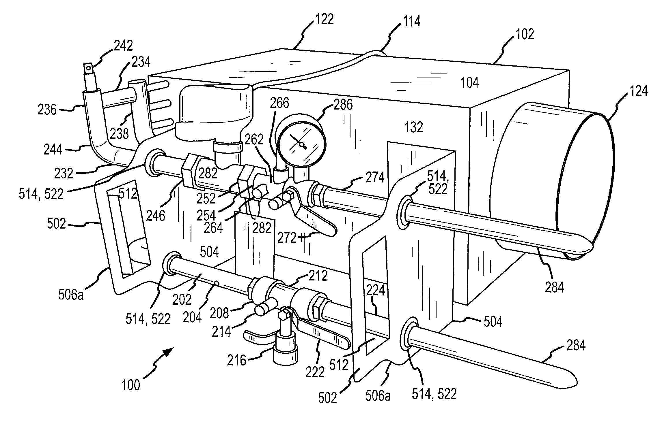
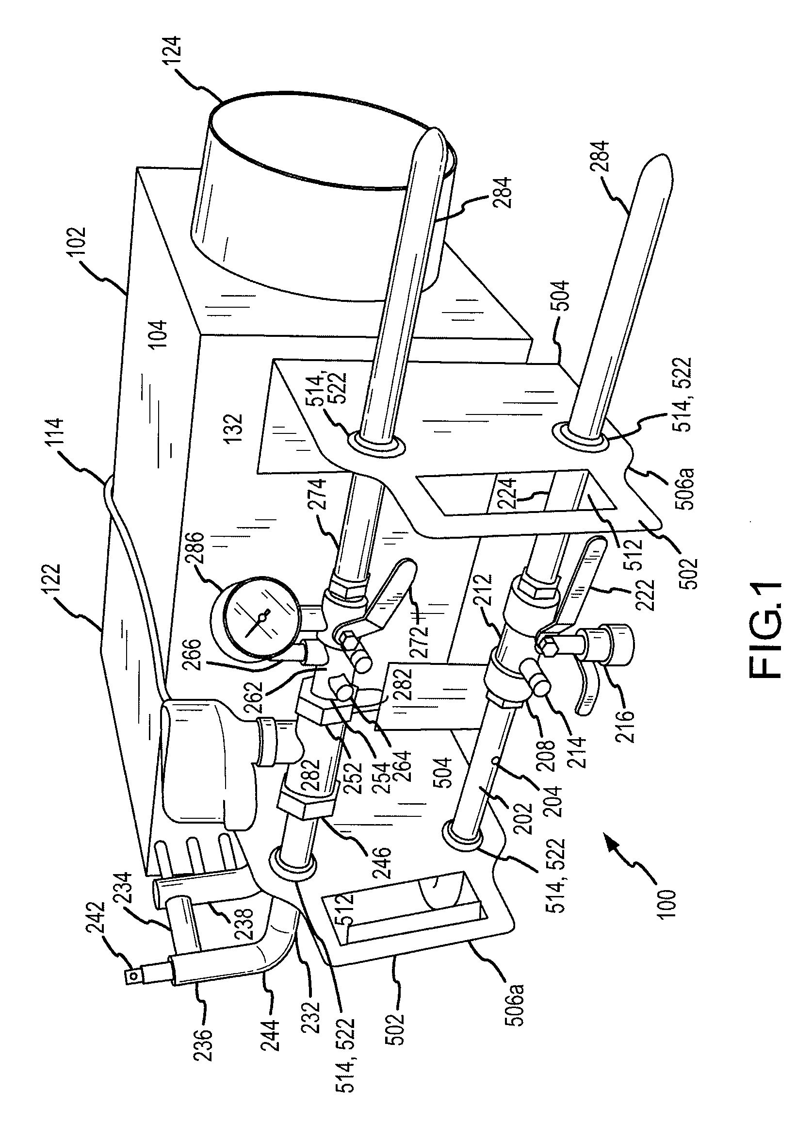
[0065]The perspective view of FIG. 1 illustrates a fully-functional HVAC terminal unit referred to by the general reference character 100. The fully-functional zone-control unit 100 depicted in FIG. 1, which illustrates one embodiment of the present invention, preferably includes a mechanical terminal unit 102 having a casing 104 visible in FIG. 1. The casing 104, which can be made from various materials of differing thicknesses, is frequently made from galvanized sheet steel material. Frequently, the casing 104 is lined with a thermal insulation material, not visible in FIG. 1, which may be chosen from various different types such as fiberglass insulation, rigid duct board fiber insulation, polyolefin, closed cell, foam insulation, etc. In some embodiments, insulation contained in zone-control unit 100 complies with an industry standard, such as a standard set by the Office of Statewide Health and Planning Department (OSHPOD).

[0066]For VAV zone-control units 100, the mechanical ter...


PUM


Abstract

A zone-control unit for use in a heating, ventilation, and air conditioning (HVAC) system, the zone-control unit includes a heat exchanger, an inlet piping assembly coupled with the heat exchanger for supplying fluid to the heat exchanger, an outlet piping assembly coupled with the heat exchanger for receiving fluid from the heat exchanger, a bracket that maintains the inlet piping assembly and the outlet piping assembly in positional relationship, and an ancillary component coupled with the heat exchanger.

Description

CROSS-REFERENCES TO RELATED APPLICATIONS[0001]This application is a nonprovisional of, and claims the benefit of priority from, U.S. Provisional Patent Application No. 60 / 884,366 filed Jan. 10, 2007 (Attorney Docket No. 025920-000600US). This application is related to U.S. patent application Ser. No. 11 / 429,418 filed May 5, 2006 (Attorney Docket No. 025920-000120US), U.S. patent application Ser. No. 11 / 180,310 filed Jul. 12, 2005 (Attorney Docket No. 025920-000210US), U.S. Pat. No. 6,951,324 (Attorney Docket No. 025920-000200US), U.S. patent application Ser. No. 10 / 857,211 filed May 24, 2004 (Attorney Docket No. 025920-000300US), U.S. patent application Ser. No. 11 / 567,301 filed Dec. 6, 2006 (Attorney Docket No. 025920-000310US), U.S. Pat. No. 7,140,236 (Attorney Docket No. 025920-000400US), U.S. patent application Ser. No. 11 / 560,294 filed Nov. 15, 2006 (Attorney Docket No. 025920-000410US), U.S. patent application Ser. No. 11 / 619,535 filed Jan. 3, 2007 (Attorney Docket No. 025920-...

Claims


Application Information

Patent Timeline
IPC IPC(8): F28F9/007F28D7/00B21D39/04F24F1/0063
CPCF24F1/0059F24F1/26F28F9/002Y10T29/49826B23P15/26F28F27/02Y10T29/4935F28F9/0246F24F1/0063B23P2700/09F16L3/08F24F5/0003F24F13/0245F24F13/0272F24F2221/12F24F2221/36
Inventor KARAMANOS, JOHN C.
Owner KARAMANOS JOHN C
Why Eureka
Try Eureka