Suspension Apparatus for Vehicle

a suspension apparatus and vehicle technology, applied in mechanical apparatus, shock absorbers, transportation and packaging, etc., can solve the problems of insufficient suspension apparatus in terms of improving the ride comfort of the vehicle, apparatus is not satisfactory in terms of reducing the vibration of the wheel, and the risk of dust, mud and the like entering the interior of the housing through the seal portion, so as to achieve the effect of simplifying the structur

Inactive Publication Date: 2008-07-10
TOYOTA JIDOSHA KK +1
View PDF8 Cites 50 Cited by
  • Summary
  • Abstract
  • Description
  • Claims
  • Application Information

AI Technical Summary

Benefits of technology

[0096]In the form (29), the cover tube functions as a supporting member for supporting the suspension spring. The form (29) is effective when the cover tube is made of metal, for instance. The form (29) eliminates a need of additionally providing the supporting member for supporting the suspension spring, so that the suspension apparatus with a simplified structure is realized.

Problems solved by technology

In this respect, the suspension apparatus is not satisfactory in terms of improvement of the ride comfort of the vehicle.
Accordingly, the apparatus is not satisfactory in terms of mitigation of the vibration from the wheel.
In the apparatus, however, a seal portion between a housing of the hydraulic damper and a piston rod that extends from the housing is exposed or uncovered, so that there may be a risk of entry of dust, mud and the like into an interior of the housing through the seal portion.
Thus, the apparatus is not satisfactory in terms of reliability.
While there have been described some examples of problems that the conventional suspension apparatus experience, the conventional suspension apparatus equipped with the electromagnetic actuator and the hydraulic damper suffer from various problems.

Method used


Image

  • Suspension Apparatus for Vehicle
  • Suspension Apparatus for Vehicle
  • Suspension Apparatus for Vehicle

Examples


first embodiment

1. First Embodiment

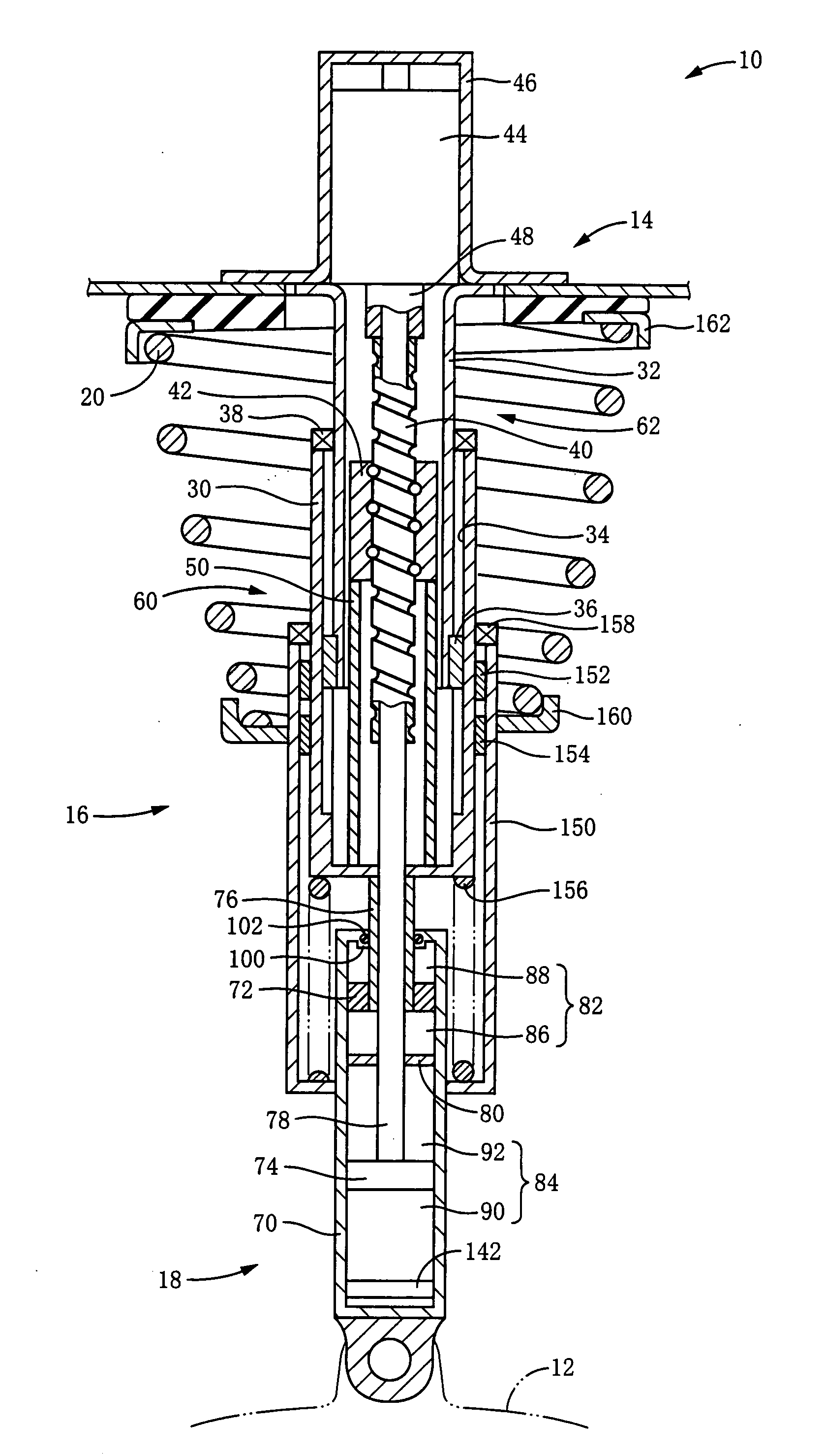
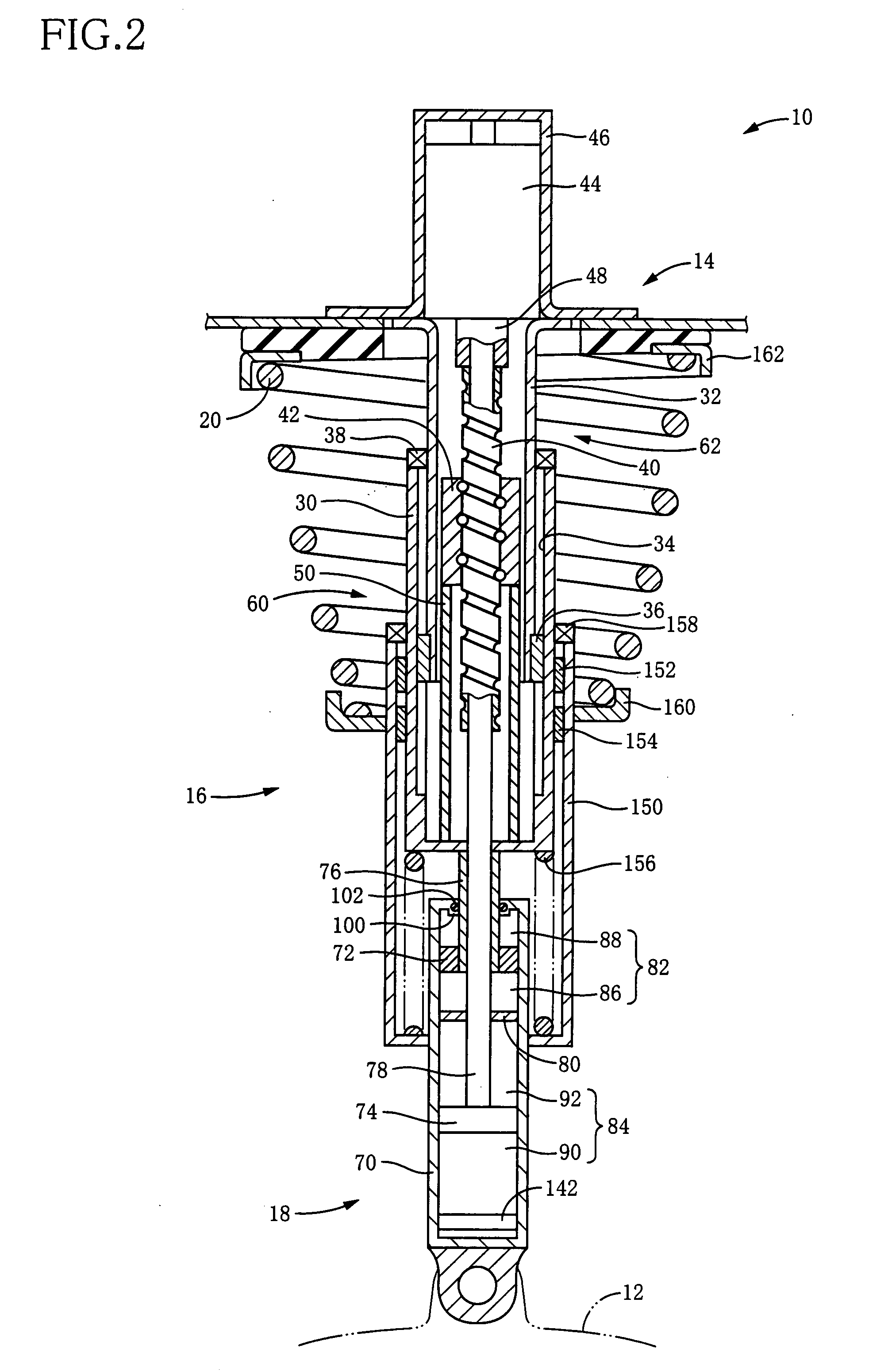
[0104]FIG. 2 shows a suspension apparatus 10 for a vehicle according to one embodiment of the present invention. The suspension apparatus 10 is of an independent suspension type and is provided for each of a front right wheel, a front left wheel, a rear right wheel, and a rear left wheel. Each suspension apparatus 10 is disposed between: a suspension lower arm (hereinafter abbreviated as “lower arm” where appropriate) 12 which is a wheel-holding member for holding a corresponding wheel and which functions as a first portion; and a mount portion 14 which is formed at a part of a body of the vehicle (such as an upper portion of a tire housing) and which functions as a second portion. The present suspension apparatus 10 is constituted by including an actuator cylinder 16 as an electromagnetic actuator, a damper cylinder 18 as a hydraulic damper, and a coil spring 20 as a suspension spring. The suspension apparatus 10 is configured such that a vibration of the vehicle...

second embodiment

2. Second Embodiment

[0120]FIG. 4 shows a suspension apparatus 180 for a vehicle according to a second embodiment. The suspension apparatus 180 of the second embodiment is substantially identical in construction with the suspension apparatus 10 of the illustrated first embodiment, except for the hydraulic damper. Accordingly, in the description of the second embodiment, the same reference numerals as used in the apparatus of the first embodiment are used to identify the corresponding components, and an explanation of which is simplified or omitted.

[0121]The suspension apparatus 180 of the exemplary embodiment is constituted principally by an actuator cylinder 182 which has a structure similar to that of the actuator cylinder 16 of the first embodiment. In other words, the actuator cylinder 182 is configured such that a wheel-side unit 188 is constituted by including an outer tube 184, a nut 42, and a supporting tube 186 while a body-side unit 194 is constituted by including a rod 192...

third embodiment

3. Third Embodiment

[0128]FIG. 6 shows a suspension apparatus 250 for a vehicle according to a third embodiment. The suspension apparatus 250 of the third embodiment is substantially identical in construction with the suspension apparatus 10 of the illustrated first embodiment, except for the hydraulic damper. Accordingly, in the description of the third embodiment, the same reference numerals as used in the apparatus of the first embodiment are used to identify the corresponding components, and an explanation of which is simplified or omitted.

[0129]The suspension apparatus 250 according to the present embodiment is constituted by including an actuator cylinder 252 as the electromagnetic actuator, a damper cylinder 254 as the hydraulic damper, and a coil spring 20 as the suspension spring. Although the actuator cylinder 252 is similar to the actuator cylinder 16 in the first embodiment, the rod 40 and the motor shaft 48 of the motor 44 in the present embodiment are not hollow, unlike...


PUM


Abstract

It is an object of the invention to improve utility in a suspension apparatus for a vehicle having an electromagnetic actuator and a hydraulic damper. In the suspension apparatus, a hydraulic damper is disposed between an electromagnetic actuator and a wheel-holding portion, and a cover tube is provided for accommodating a seal provided between a piston rod and a housing of the hydraulic damper. In the suspension apparatus according to the present invention wherein the hydraulic damper is disposed between the wheel-holding portion and the electromagnetic actuator, it is possible to effectively mitigate not only transmission of vibrations to the vehicle body from the wheel via the electromagnetic actuator but also transmission of vibrations to the electromagnetic actuator. Further, owing to the presence of the cover tube, entry of dust and the like into the hydraulic damper through the seal can be effectively prevented.

Description

TECHNICAL FIELD[0001]The present invention relates to a suspension apparatus for a vehicle constituted by including a so-called electromagnetic actuator.BACKGROUND ART[0002]As a suspension apparatus for a vehicle, there has been considered a so-called electromagnetic suspension apparatus constituted by including an electromagnetic actuator which may be called “a suspension cylinder”. Such a suspension apparatus is described in the following patent documents, for instance. The electromagnetic actuator of the suspension apparatus described in the patent documents includes: a wheel-side unit (which may be called “a wheel-side member”) coupled to a wheel-holding portion such as a suspension lower arm for holding a wheel of the vehicle; a body-side unit (which may be called “a body-side member”) coupled to a mount portion such as an upper portion of a tire housing that is formed at a part of a body of the vehicle. The wheel-side unit and the body-side unit are configured to be movable re...

Claims


Application Information

Patent Timeline
Patent Type & Authority Applications(United States)
IPC IPC(8): F16F9/00
CPCB60G15/065B60G17/0157B60G17/021F16F15/03B60G2202/32B60G2202/42B60G2202/312B60G13/08B60G15/06B60G17/00F16F9/38
Inventor INOUE, HIROFUMIKONDO, TAKUHIRO
Owner TOYOTA JIDOSHA KK
Why Eureka
Try Eureka