Laser resonator comprising an internal beam splitter

a laser resonator and beam splitter technology, which is applied in the direction of laser details, optical resonator shape and construction, electrical apparatus, etc., can solve the problems of affecting the overall performance of the laser resonator, all losses and non-usable light emission are harmful to the overall performance, and the maximum achievable output power or power density, respectively, is way too low for numerous applications, and achieves better beam quality and spectral characteristics. , the effect of improving the output power

Inactive Publication Date: 2008-07-10
RAAB VOLKER
View PDF4 Cites 10 Cited by
  • Summary
  • Abstract
  • Description
  • Claims
  • Application Information

AI Technical Summary

Benefits of technology

[0007]A simple and compact laser resonator is provided by the present invention which makes it possible to symmetrically operate a gain medium, preferably a semiconductor, which possesses more than one channel of emission. As a result higher output powers and / or better beam qualities and / or better spectral characteristics can be achieved.

Problems solved by technology

Improving single parameters generally deteriorates others.
Generally speaking all losses and not usable emission of light is harmful for the overall performance.
However, presently the maximum achievable output power or the power density, respectively, is way too low for numerous applications.
On increasing the pump powers the resulting optical power densities would destroy the device.
The apparent solution to increase the active volume is practically limited because the modal selectivity of the resonator decreases and the beam quality deteriorates correspondingly.
The fraction of radiation that is emitted towards the feedback cannot be influenced and, therefore, is too high or too low as compared to the optimal amount.
If the fraction towards the feedback is too high, that is it is above the saturation, the output power lacks this excess power.
But if it is too low then the beam quality and side mode suppression suffer.

Method used


Image

  • Laser resonator comprising an internal beam splitter
  • Laser resonator comprising an internal beam splitter
  • Laser resonator comprising an internal beam splitter

Examples


Embodiment Construction

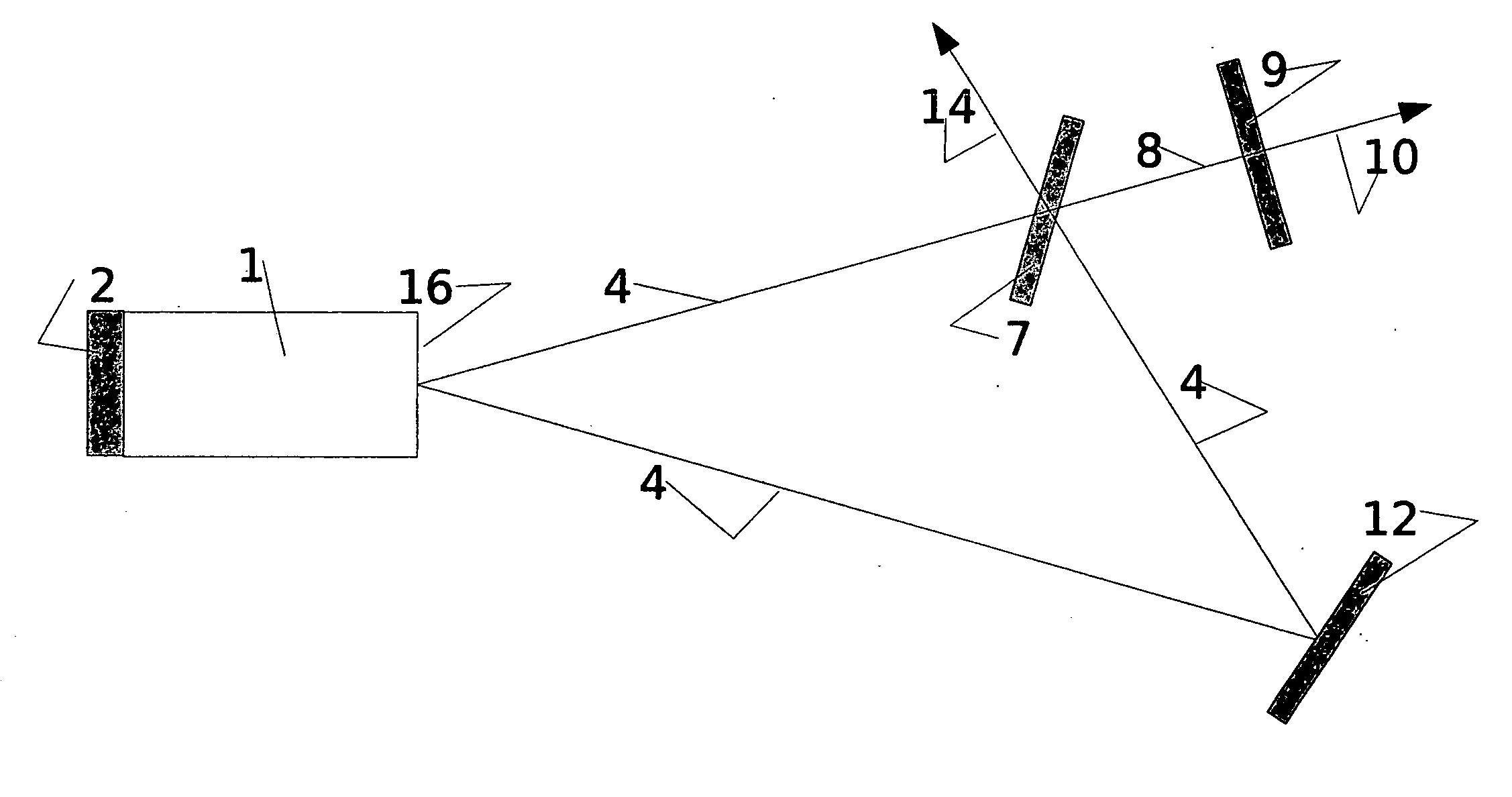
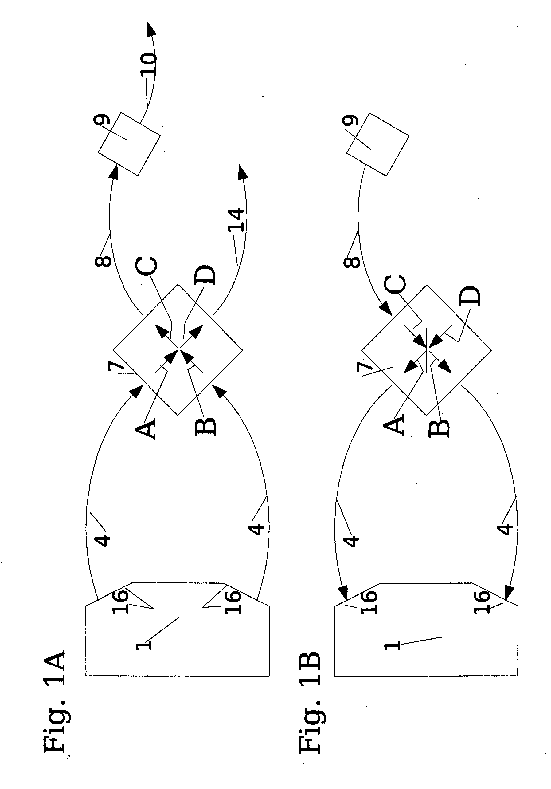
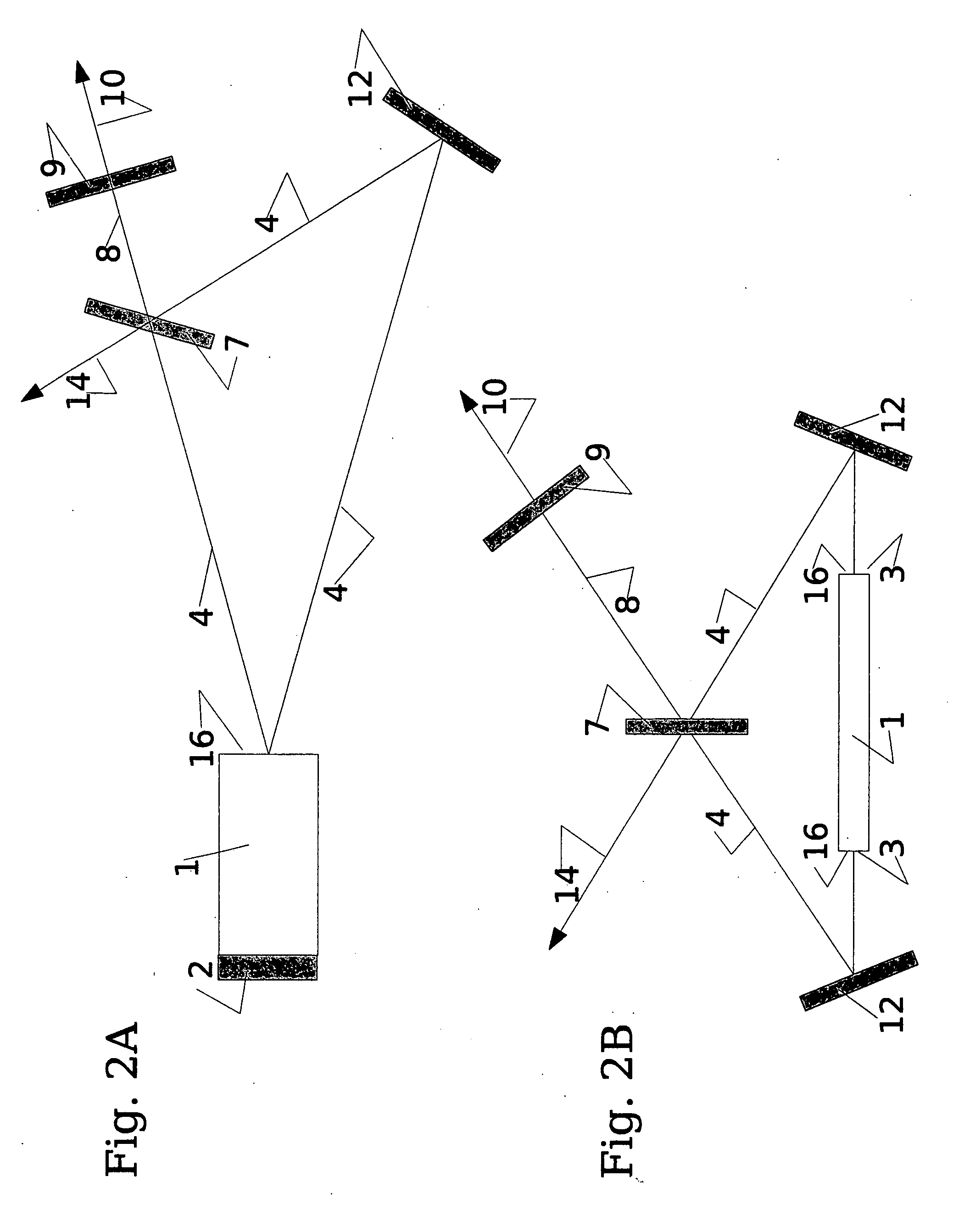
[0031]A principal depiction of the concept of the laser resonator of the present invention is given in FIG. 1A which shows the light path from the gain 1 to the feedback element 9. FIG. 1B indicates the reverse. The gain 1 material is characterized by its ability to react with stimulated emission to feedback. It may be a setup or arrangement with or without its own resonator. That means that in the following paragraphs generally no distinction is made between setups that are externally forced to resonate at a given laser emission, usually called “seeding” or regenerative amplifier, and setups in which the resonators are completed only by the external feedback. If a distinction with respect to the gain 1 is made at all, then the former will be called “laser” and the latter “semi-open laser” to emphasize the fact that the latter is missing feedback on one side. A laseractive gain 1 possesses at least one surface 16 through which at least two different beams 4 can couple in and out. Fo...


PUM


Abstract

A simple and compact laser resonator is proposed which makes it possible to symmetrically operate a gain medium, preferably a semiconductor, which possesses more than one channel of emission. As a result higher output powers and/or better beam qualities and/or better spectral characteristics can be achieved. The resonator is very compact and ideally comprises only three optical elements: a laseractive gain medium (1), a cylindrical collimation lens (5), and a prism (6) which is adapted to the angle between the two emissions (4) and which carries a beam splitter (7) and a feedback mirror (9) on its faces. Preferably the gain medium (1) possesses a feedback element (2) and an antireflective coating (3) on its faces. If no antireflective coating (11) is desired the same effect can be achieved by arranging the angle of incidence to fulfill the Brewster-condition. In a preferred embodiment the gain medium (1) is a high-power diode laser chip with an internal stripe-array and/or the laser resonator is unstable along the direction parallel to the epitaxial layers. In alternative embodiments the feedback element (9) is wavelength selective like a grating, a dielectric filter, a holographic element or a volume Bragg grating.

Description

CROSS-REFERENCE TO RELATED APPLICATION[0001]This is a continuation-in-part application of international application PCT / DE2005 / 001959 filed Oct. 28, 2005 and claiming the priority of German application 10 2004 053 136.6 filed Oct. 29, 2004.BACKGROUND OF THE INVENTION[0002]Each laser comprises a laser active region called gain in which the supplied energy is converted to coherent radiation by means of stimulated emission. On this behalf an optical resonator is necessary which re-injects part of the radiation back into the gain region. This resonator comprises at least one feedback element, typically a semitransparent mirror. The resonator determines the physical characteristics of the laser radiation by means of its geometry and feedback characteristics. The most prominent radiation characteristics are the spatial profile, the wavelength, and the polarization. The achievable parameters strongly depend on the gain material and the resonator and are usually inversely correlated with ea...

Claims


Application Information

Patent Timeline
Patent Type & Authority Applications(United States)
IPC IPC(8): H01S5/10
CPCH01S3/08H01S3/0811H01S3/0818H01S3/082H01S3/0823H01S5/4056H01S5/1064H01S5/1089H01S5/14H01S5/141H01S5/10
Inventor RAAB, VOLKER
Owner RAAB VOLKER
Why Eureka
Try Eureka