Intraluminal medical device having variable axial flexibility about the circumference of the device

a medical device and axial flexibility technology, applied in the field of expandable intraluminal medical devices, can solve the problems of stent fatigue failure, metal cracking, and strain experienced by each strut member, and achieve the effect of facilitating device orientation

Active Publication Date: 2008-07-10
CARDINAL HEALTH SWITZERLAND 515 GMBH
View PDF12 Cites 18 Cited by
  • Summary
  • Abstract
  • Description
  • Claims
  • Application Information

AI Technical Summary

Benefits of technology

[0015]The device of the present invention, provided with a relatively stiff axial region and a relatively flexible axial region facilitates device orientation, a desirable feature as it travels (1) through curves or bifurcations in the vessel, (2) over curves or bends in the guidewire, or (3) traverses other eccentricities located within the vessel that force the member into a curved path. So long as the device possesses a sufficient degree of freedom to rotate about its longitudinal axis, it will assume the path of least resistance in the course of its travel, and thereby rotate / orient itself to conform to the bend in the vessel. Thus, orientation of the device can be attained as a result of device rotation to align the relatively flexible regions of the device to the bending direction of the vessel or guidewire.
[0016]Aside from being adapted to pass relatively easily through bends and curves in the vasculature, the device can be used in a number of beneficial ways. A device, such as a stent that is deployed at the site of or in the vicinity of a bifurcation may have circumferentially asymmetrical design features intended to conform to the bifurcation, and in particular, the side branch ostium. Such devices must be deployed in the proper circumferential orientation, a result that can be obtained by providing the vessel with a relatively stiff region and a relatively flexible region, thereby allowing the device to self-orient to the curve in the vessel. The self-orienting nature is useful where the bend, so to speak, is imparted by the guidewire, which passes through the device. For example, the device may travel over a guide wire passed into a bifurcation side branch, allowing a properly oriented device to be deployed in its in the side branch. In yet another example, a guidewire having a prebent section can be used to effect orientation of the device in situations where vessel characteristics are not of an orientation-producing nature. In other words, by positioning the bend in the guidewire at the desired location, the device will orient itself as it traverses the bend. This arrangement is advantageous where it is desirable to achieve orientation in a relatively straight vessel segment. In any event, with these arrangements, rotation of the device for positioning purposes, whether for deployment or other medically useful purpose is facilitated.

Problems solved by technology

While the geometry of the stent members is uniform, under load, the strain experienced by each strut member is not.
High stress and / or strain can cause cracking of the metal and potential fatigue failure of the stent under the stress of a beating heart.
In any event, a bifurcation or bend in a vessel can present challenges if an implant is to be deployed there.

Method used


Image

  • Intraluminal medical device having variable axial flexibility about the circumference of the device
  • Intraluminal medical device having variable axial flexibility about the circumference of the device
  • Intraluminal medical device having variable axial flexibility about the circumference of the device

Examples


Embodiment Construction

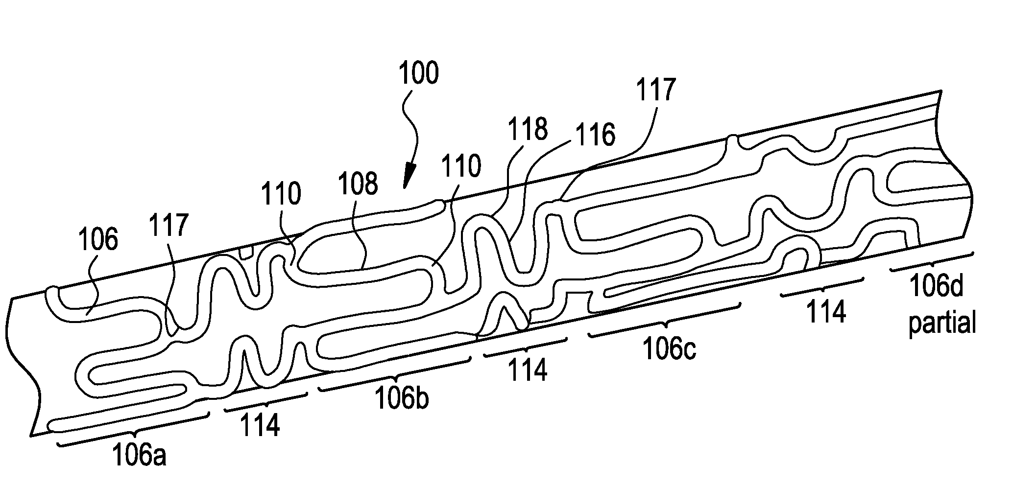
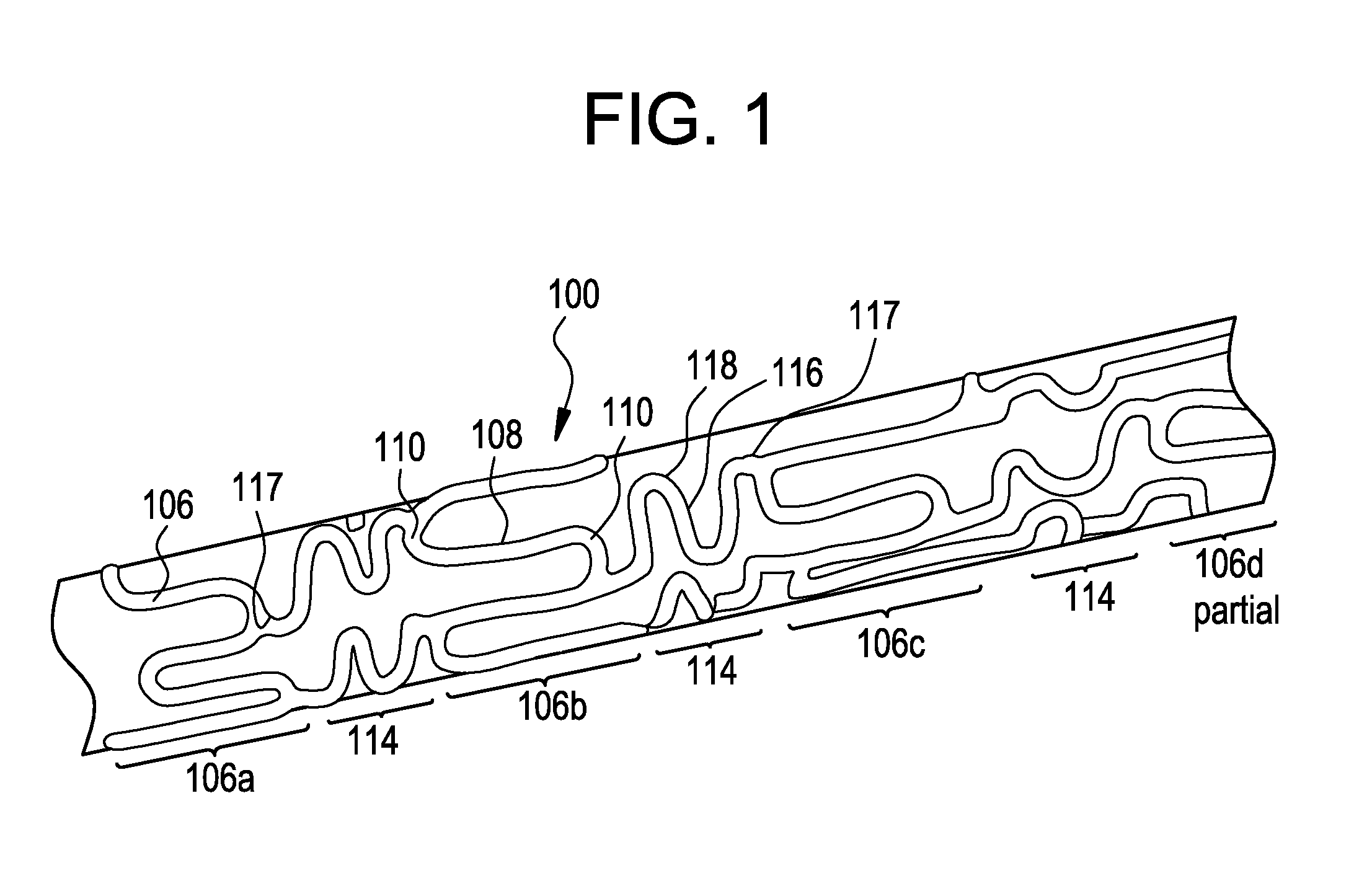
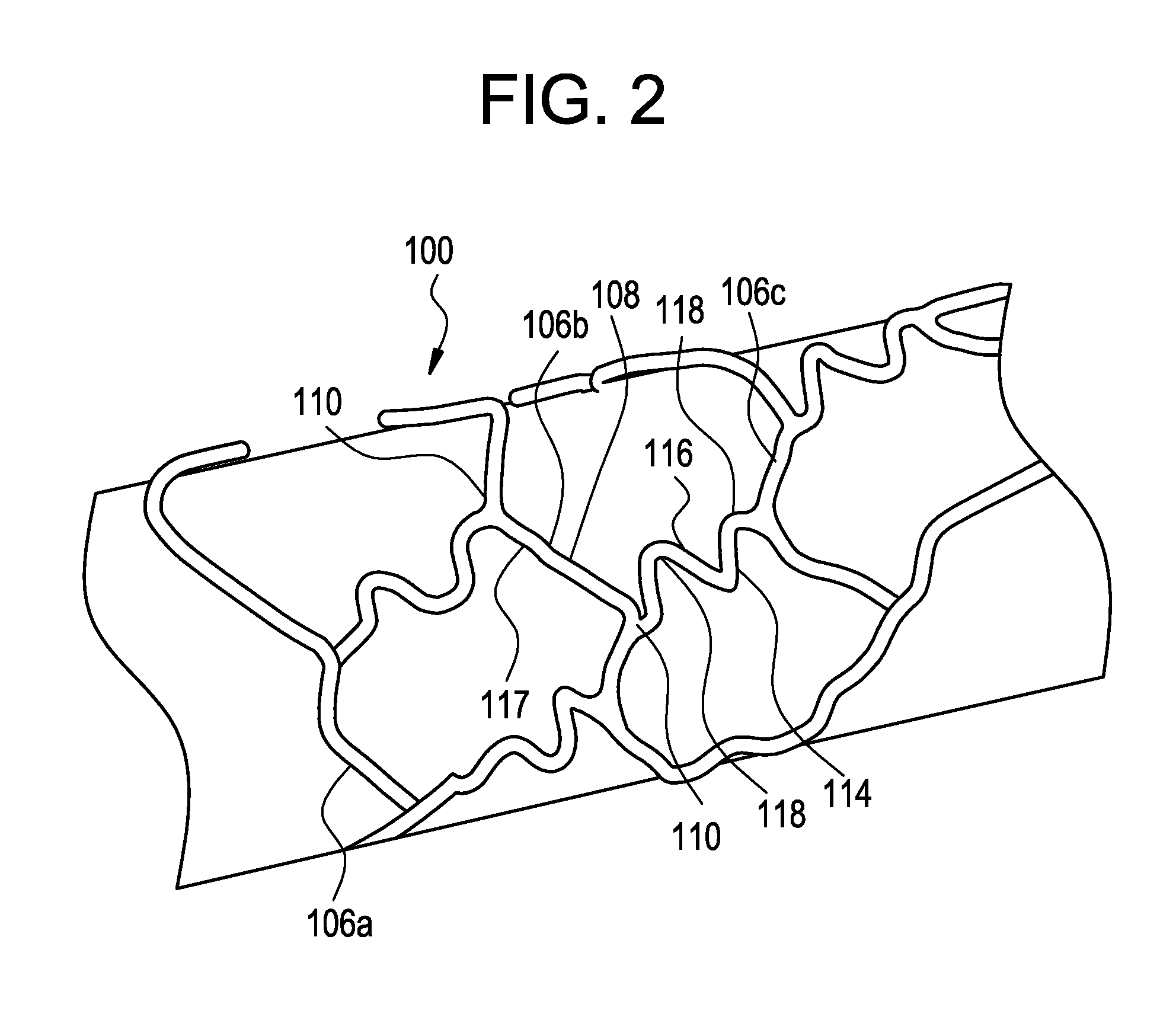
[0030]FIG. 1 shows an exemplary medical device, here a stent, illustrating a device that can be modified in accordance with the present disclosure. The medical device 100 comprises one or more hoop components 106 having a tubular configuration with proximal and distal open ends defining a longitudinal axis extending therebetween. Each hoop component is formed as a continuous series of substantially longitudinally oriented radial strut members 108 and a plurality of radial arc members 110 connecting adjacent radial struts.

[0031]The device of the present invention includes connecting elements 114 joined to longitudinally adjacent hoop components 106. In this specific depiction, adjacent flexible struts 116 are connected at opposite ends in a waveform-like pattern shown here as substantially N-shaped. As illustrated, the plurality of flexible arc members 118 of connecting elements 114 have a substantially semi-circular configuration and are substantially symmetric about their centers, ...


PUM


Abstract

This invention concerns expandable intraluminal medical devices for use within a body passageway or duct, wherein the devices exhibit differing degrees of flexibility around the circumference of the device.

Description

FIELD OF THE INVENTION[0001]This invention concerns an expandable intraluminal medical device for use within a body passageway or duct in which the device has regions that exhibit differing degrees of flexibility about the device.BACKGROUND OF THE INVENTION[0002]The use of intraluminal prosthetic devices has been demonstrated to present an alternative to conventional vascular surgery. Intraluminal prosthetic devices are commonly used in the repair of aneurysms, as liners for vessels, or to provide mechanical support and prevent the collapse of stenosed or occluded vessels.[0003]Intraluminal endovascular prosthetics involve the percutaneous insertion of a generally tubular prosthetic device, such as a stent, into a vessel or other tubular structure within the vascular system. The stent is typically delivered to a specific location inside the vascular system in a low profile (pre-deployed) state by a catheter. Once delivered to the desired location, the stent is deployed by expanding ...

Claims


Application Information

Patent Timeline
Patent Type & Authority Applications(United States)
IPC IPC(8): A61F2/06
CPCA61F2/91A61F2/915A61F2250/0029A61F2250/0018A61F2002/91558
Inventor MARREY, RAMESH V.KREVER, MATTHEW E.OLSEN, DANIELBURGERMEISTER, ROBERT
Owner CARDINAL HEALTH SWITZERLAND 515 GMBH
Why Eureka
Try Eureka