Temperature measurement and control of wafer support in thermal processing chamber

Active Publication Date: 2008-07-17
APPLIED MATERIALS INC
View PDF17 Cites 38 Cited by
  • Summary
  • Abstract
  • Description
  • Claims
  • Application Information

AI Technical Summary

Benefits of technology

[0013]Yet another embodiment of the present invention provides a method for uniformly heating a substrate to a target temperature comprising positioning the substrate in a processing chamber connected with a first heat so

Problems solved by technology

Particularly, it may be necessary to heat a substrate at a temperature between about 200° C. to about 1350° C. with a temperature deviation of about 1° C. to 1.5° C. The state of the art RTP systems have difficulties to reach this kind of uniformity, especially near the edge of the substrate.
The edge ring and the substrate overlap producing a complicated heating

Method used


Image

  • Temperature measurement and control of wafer support in thermal processing chamber
  • Temperature measurement and control of wafer support in thermal processing chamber
  • Temperature measurement and control of wafer support in thermal processing chamber

Examples


Example

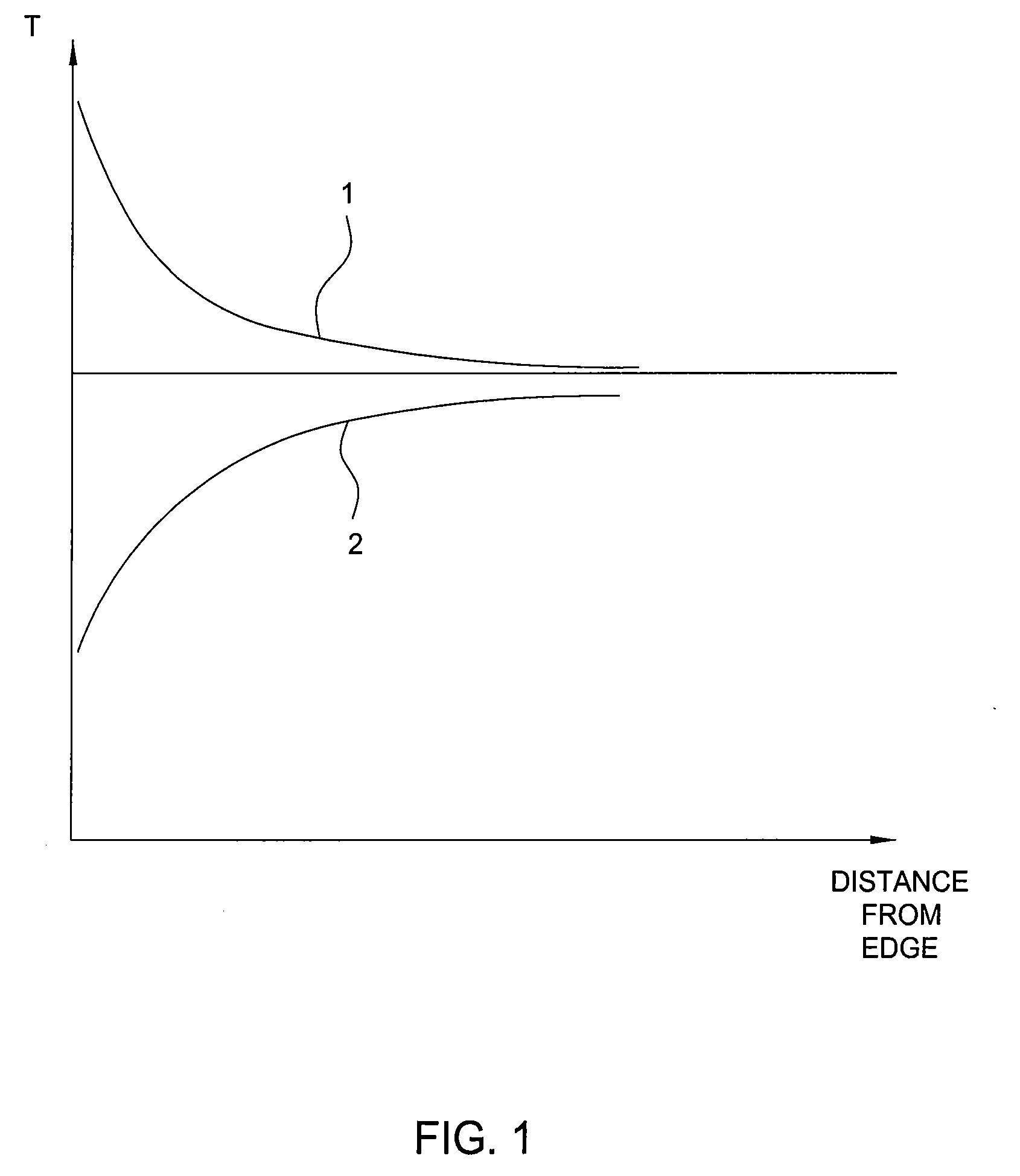
[0019]The present invention provides apparatus and methods for achieving uniform heating to a substrate during a rapid thermal process. More particularly, the present invention provides apparatus and methods for controlling the temperature of an edge ring supporting a substrate during a rapid thermal process to improve temperature uniformity across the substrate.

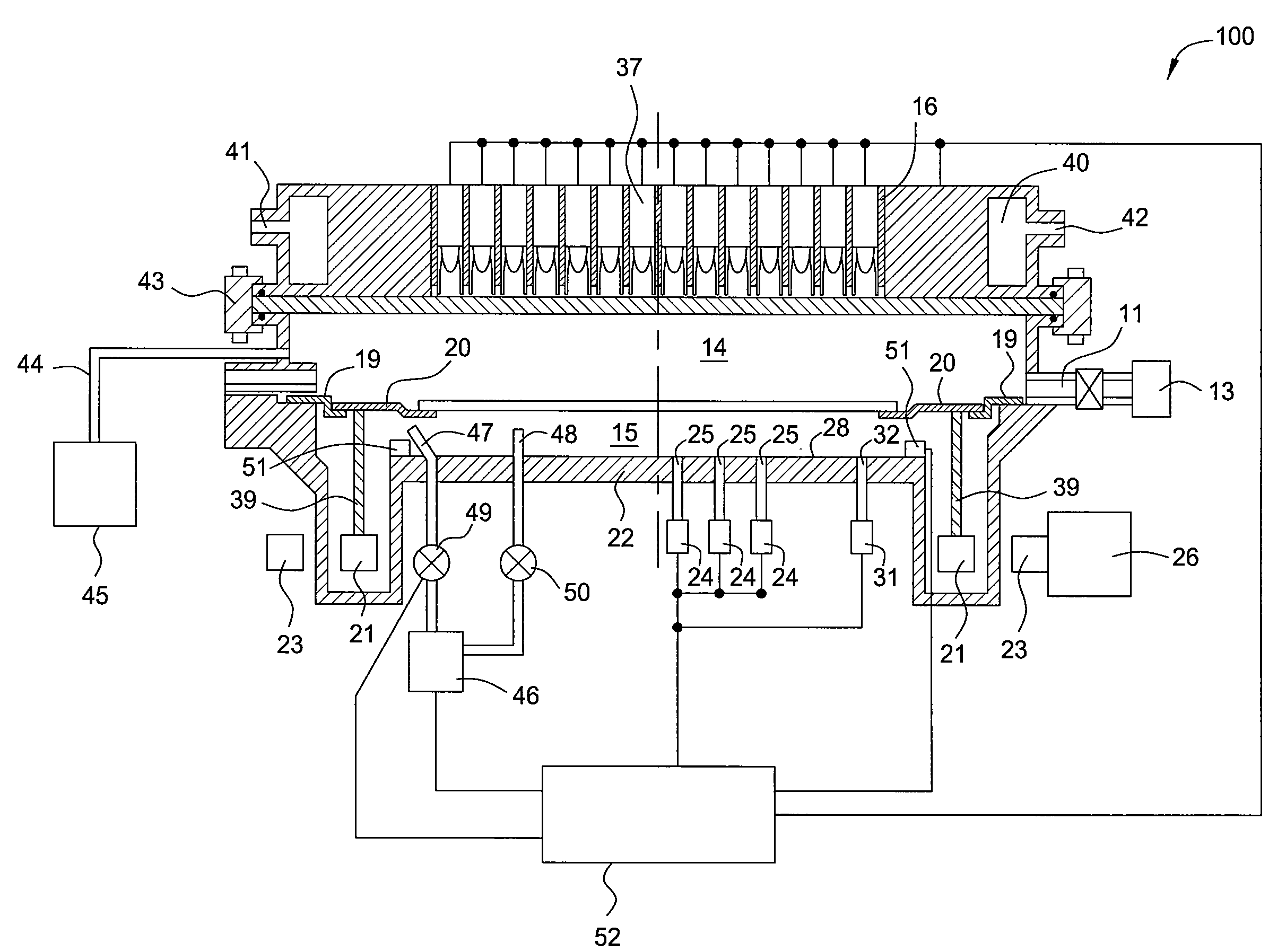
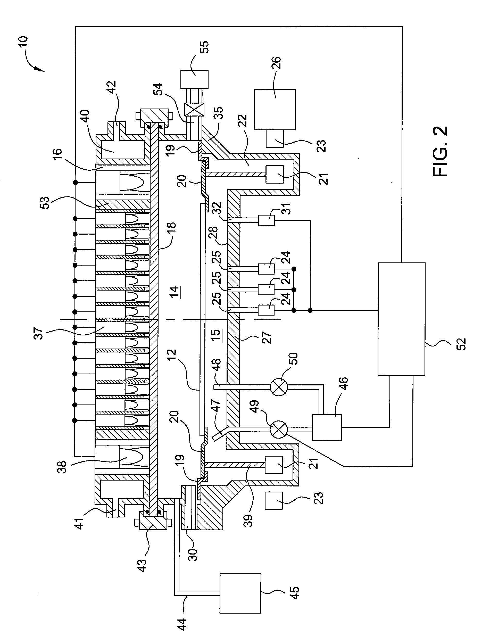
[0020]FIG. 2 schematically illustrates a sectional view of a rapid thermal processing system 10 in accordance with one embodiment of the present invention. The rapid thermal processing system 10 comprises a chamber body 35 defining a processing volume 14 configured for annealing a disk-shaped substrate 12 therein. The chamber body 35 may be made of stainless steel and may be lined with quartz. The processing volume 14 is configured to be radiantly heated by a heating assembly 16 disposed on a quartz window 18 of the rapid thermal processing system 10. In one embodiment, the quartz window 18 may be water cooled.

[0021]A slit v...


PUM

PropertyMeasurementUnit
Temperatureaaaaaaaaaa

Abstract

The present invention provides apparatus and methods for achieving uniform heating to a substrate during a rapid thermal process. More particularly, the present invention provides apparatus and methods for controlling the temperature of an edge ring supporting a substrate during a rapid thermal process to improve temperature uniformity across the substrate.

Description

BACKGROUND OF THE INVENTION[0001]1. Field of the Invention[0002]The present invention generally relates to the field of semiconductor processing. More particularly, the present invention relates to methods and apparatus for thermally processing a semiconductor substrate.[0003]2. Description of the Related Art[0004]Rapid thermal processing (RTP) is a process for annealing substrates during semiconductor processing. During RTP, thermal radiation is generally used to rapidly heat a substrate in a controlled environment to a maximum temperature of up to about 1350° C. This maximum temperature is maintained for a specific amount of time ranging from less than one second to several minutes depending on the process. The substrate is then cooled to room temperature for further processing. High intensity tungsten halogen lamps are commonly used as the source of heat radiation. The substrate may be provided additional heat by a heated susceptor conductively coupled to the substrate.[0005]The ...

Claims


Application Information

Patent Timeline
IPC IPC(8): A21B2/00
CPCH01L21/67248H01L21/67115H01L21/02H01L22/00H01L21/324
Inventor HUNTER, AARON MUIRADAMS, BRUCE E.BEHDJAT, MEHRANRAMANUJAM, RAJESH S.RANISH, JOSEPH M.
Owner APPLIED MATERIALS INC
Why Eureka
Try Eureka