Hydraulic control device of construction machine

a technology of hydraulic control device and construction machine, which is applied in the direction of fluid coupling, servomotor, coupling, etc., can solve the problem that the operator cannot easily feel the shock of overshoot, and achieve the effect of facilitating shock, favorable maintaining meter-in operability, and simplifying the structur

Inactive Publication Date: 2008-07-24
KOBELCO CONSTR MASCH CO LTD
View PDF1 Cites 10 Cited by
  • Summary
  • Abstract
  • Description
  • Claims
  • Application Information

AI Technical Summary

Benefits of technology

[0025]According to the above configuration, since the control valve also serves as the bypass switching means, a structure is simplified at the rate. It is possible to surely interlock the action of the control valve and open-close switching of the bypass line.
[0026]As mentioned above, the present invention has the means for maintaining the flow rate control valve in a clos...

Problems solved by technology

Even if overshoot is caused in the opening action, since the opening action is an action in the transferri...

Method used


Image

  • Hydraulic control device of construction machine
  • Hydraulic control device of construction machine
  • Hydraulic control device of construction machine

Examples


first embodiment

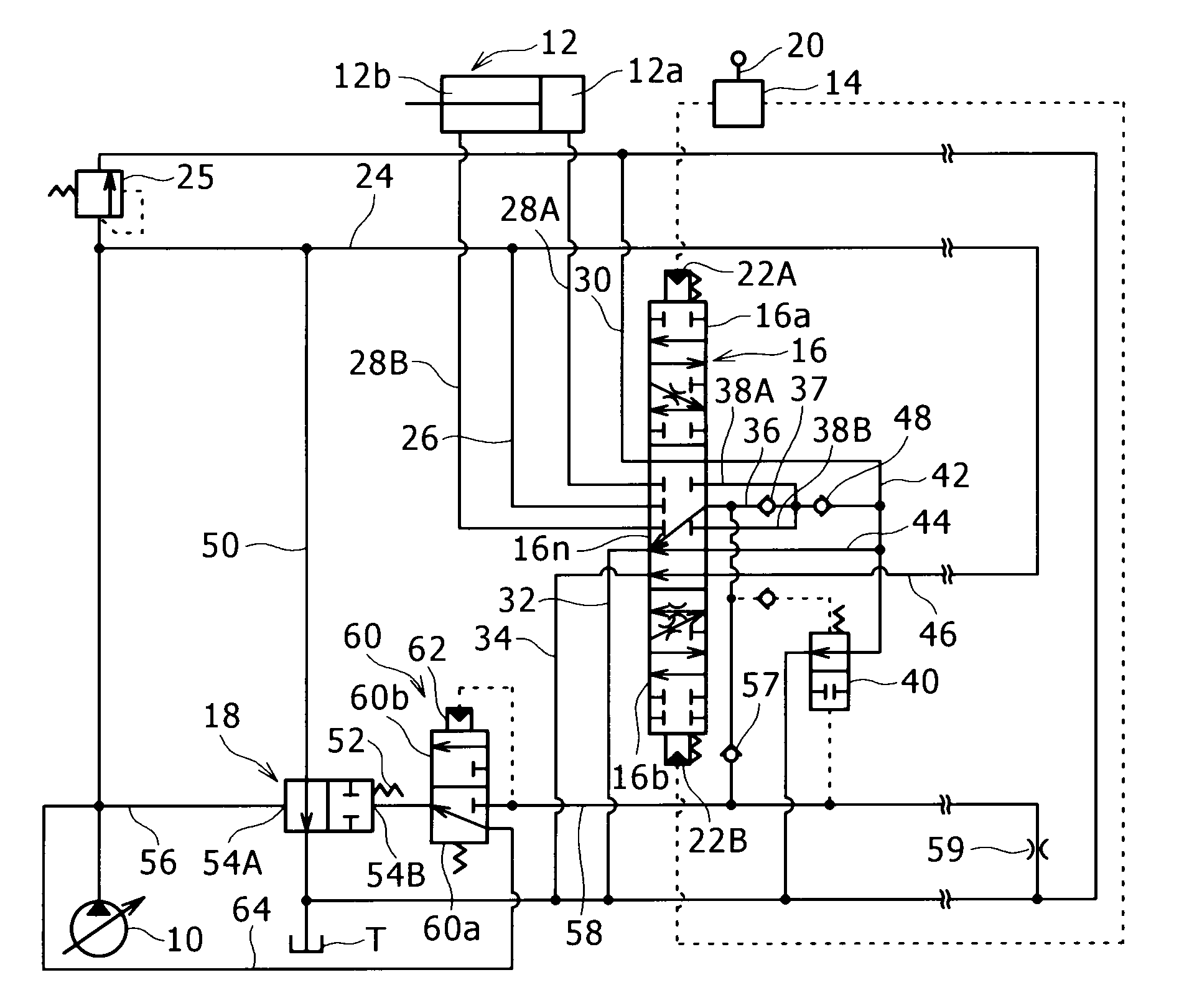
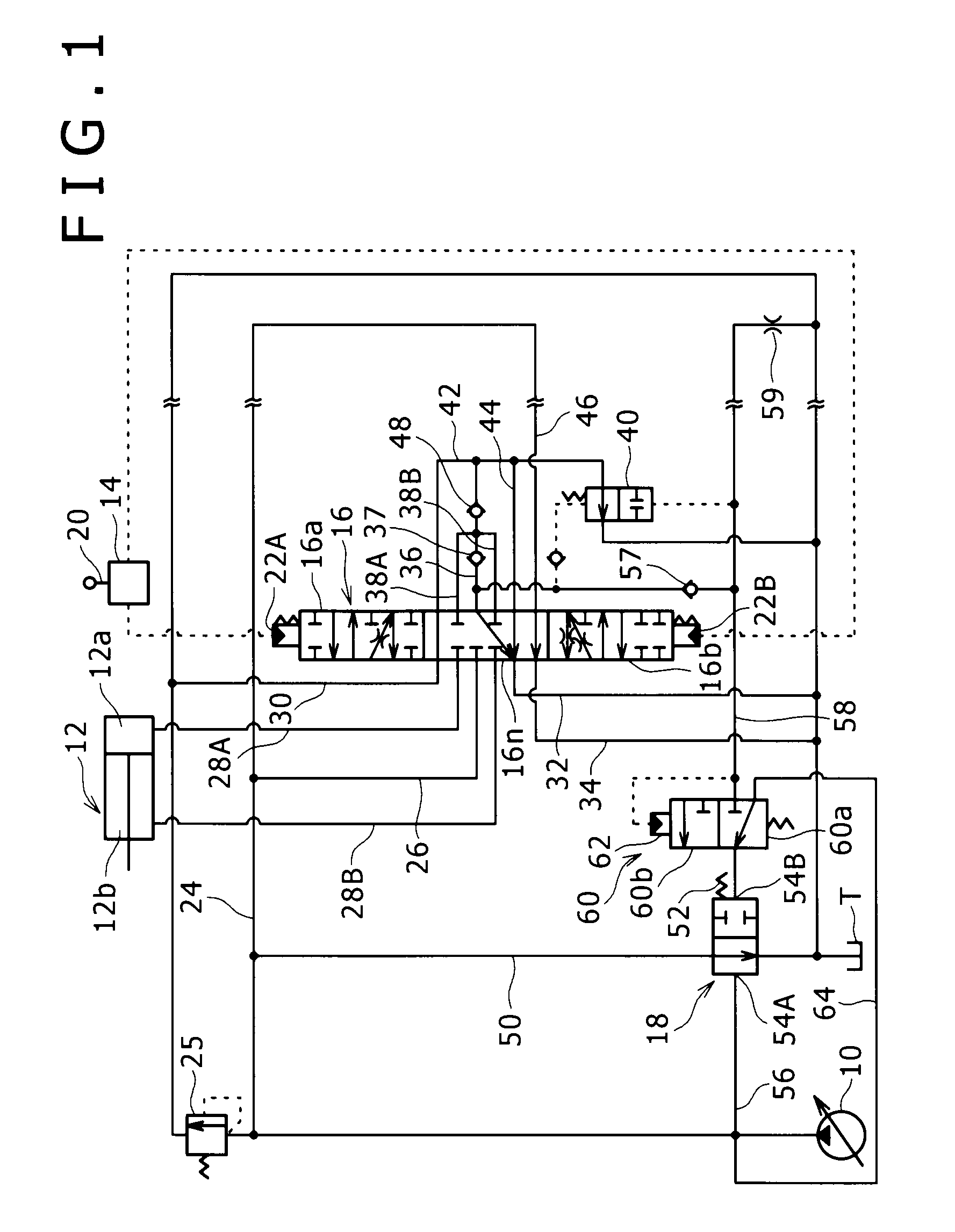
[0030]A description will be given to the present invention with reference to FIG. 1.

[0031]FIG. 1 is a circuit diagram showing a hydraulic control device according to the first embodiment of the present invention. The hydraulic control device is to control a flow rate of working oil supplied from a hydraulic pump 10 mounted in a construction machine to a hydraulic cylinder 12 serving as a hydraulic actuator, and provided with a remote control valve 14, a control valve 16 and a flow rate control valve 18.

[0032]The hydraulic pump 10 is formed of a variable capacity type hydraulic pump in an example of the figure. A capacity thereof is controlled by a regulator (not shown). However, the present invention is not limited to application of the variable capacity type hydraulic pump, but a fixed capacity type hydraulic pump can also be applied. The hydraulic actuator according to the present invention is also not limited the hydraulic cylinder 12, but for example a hydraulic motor to which t...


PUM


Abstract

A hydraulic control device of construction machine is provided with a control valve lying between a hydraulic pump and a hydraulic actuator for opening and closing a meter-in control flow path, and a flow rate control valve lying between a pump discharge line on the upstream side of the above control valve and a tank. The above flow rate control valve receives a pump pressure and a load sensing pressure corresponding to a pressure on the downstream side of the meter-in control flow path as a pilot pressure, and is activated for opening and closing so as to maintain a constant differential pressure therebetween. The above flow rate control valve is maintained in a closed state by a pilot pressure switching valve when the load sensing pressure is low. The above control valve opens a bypass line when the meter-in control flow path is closed.

Description

BACKGROUND OF THE INVENTION[0001]1. Field of the Invention[0002]The present invention relates to a device for controlling a flow rate of working oil supplied from a hydraulic pump mounted in a construction machine such as a hydraulic excavator to a hydraulic actuator.[0003]2. Description of the Related Art[0004]As a device for controlling a flow rate of working oil supplied from a hydraulic pump mounted in a construction machine such as a hydraulic excavator to a hydraulic actuator, a technique described in Japanese Patent Laid-Open No. Hei8-93705 is known for example. A flow rate control valve for transferring a part of discharge oil of the hydraulic pump to a tank controls the flow rate of the working oil in a flow path so as to maintain a constant differential pressure between a discharge pressure thereof and a load pressure of the hydraulic actuator. In the above flow rate control, irrespective of a change in a load of the hydraulic actuator, it is possible to supply the working...

Claims


Application Information

Patent Timeline
IPC IPC(8): F15B15/18F16D31/02F15B11/00E02F9/22F15B21/00F15B1/26
CPCF15B11/055F15B2211/8606F15B2211/3116F15B2211/31576F15B2211/329F15B2211/351F15B2211/40515F15B2211/413F15B2211/41563F15B2211/428F15B2211/45F15B2211/6051F15B2211/6355F15B2211/851F15B2211/3055
Inventor UMEZU, YOSHIYASUTOJI, YUTAKA
Owner KOBELCO CONSTR MASCH CO LTD
Why Eureka
Try Eureka