Electrohydraulic Aggregate with a Compact Construction

a technology of electrohydraulic aggregate and compact structure, which is applied in the direction of bearing unit rigid support, positive displacement liquid engine, piston pump, etc., can solve the disadvantageous effect of increasing the diameter of the axial direction and the increase of the diameter so as to reduce the inertia effect and unbalance effect, reduce the mass of the direct-current motor, and reduce the overall length

Inactive Publication Date: 2008-07-24
CONTINENTAL TEVES AG & CO OHG
View PDF14 Cites 13 Cited by
  • Summary
  • Abstract
  • Description
  • Claims
  • Application Information

AI Technical Summary

Benefits of technology

[0018]The solution with a reduced overall length is improved further when the rotor includes a winding support with an accommodation for the B-bearing, with the B-bearing being provided in such a manner that it is substantially completely integrated in the winding support in an axial direction.
[0019]In order to reduce the mass of the direct-current motor with a given stability, it is proposed in a furthermore favorable fashion to make the winding support of a sintered material with low density. This measure will reduce inertia effects and unbalance effects for a long time. Further reduction in the mass of the direct-current motor can be achieved when the shaft and the winding support, being composed of the sintered material, have an integral design.
[0020]As is furthermore shown in a favorably compact design of the invention, the rotor has an axial commutator, and the axial commutator is contacted by carbon brushes being arranged in parallel to the axle in tubular cases in the at least one through-hole. The cases can be arranged fixedly at an electronic control unit of the aggr

Problems solved by technology

A disadvantageous effect of this measure resides in that the diameter of the direct-current motor grows because the diameter of the recess must be dimensioned in such a fashion that the carbon brushes in their full overall length are received so as to be integrated in the rotor

Method used


Image

  • Electrohydraulic Aggregate with a Compact Construction
  • Electrohydraulic Aggregate with a Compact Construction
  • Electrohydraulic Aggregate with a Compact Construction

Examples


Embodiment Construction

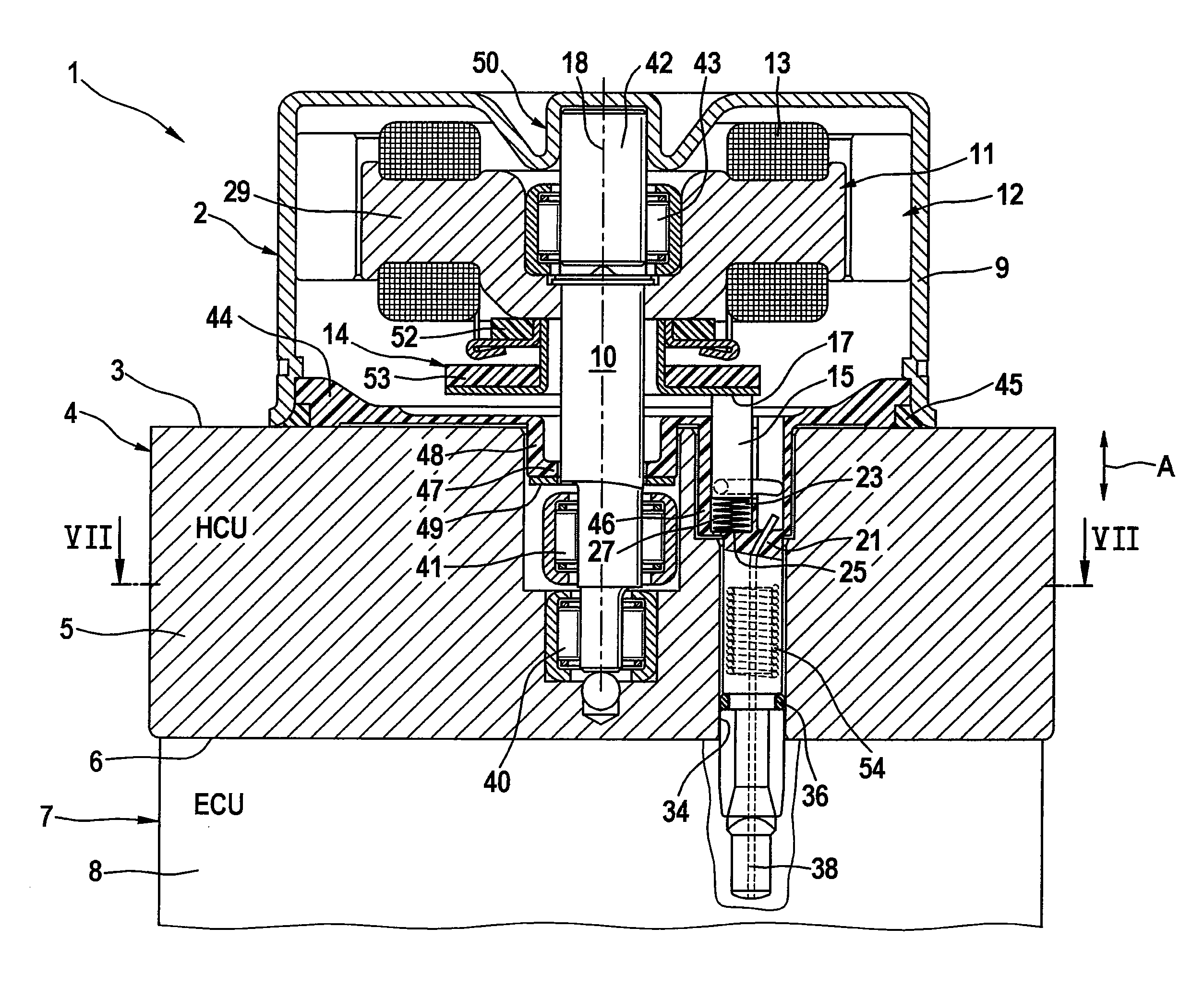
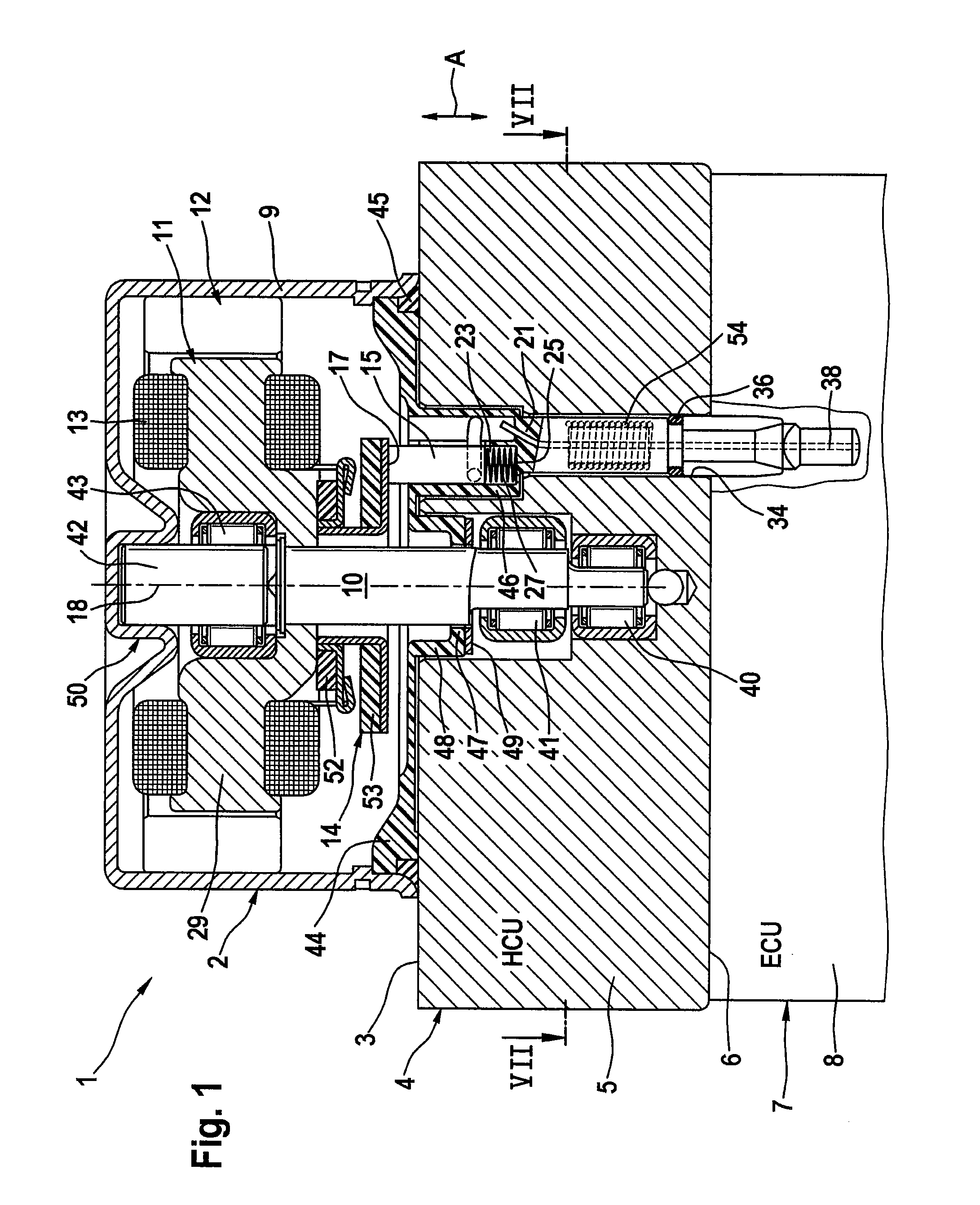
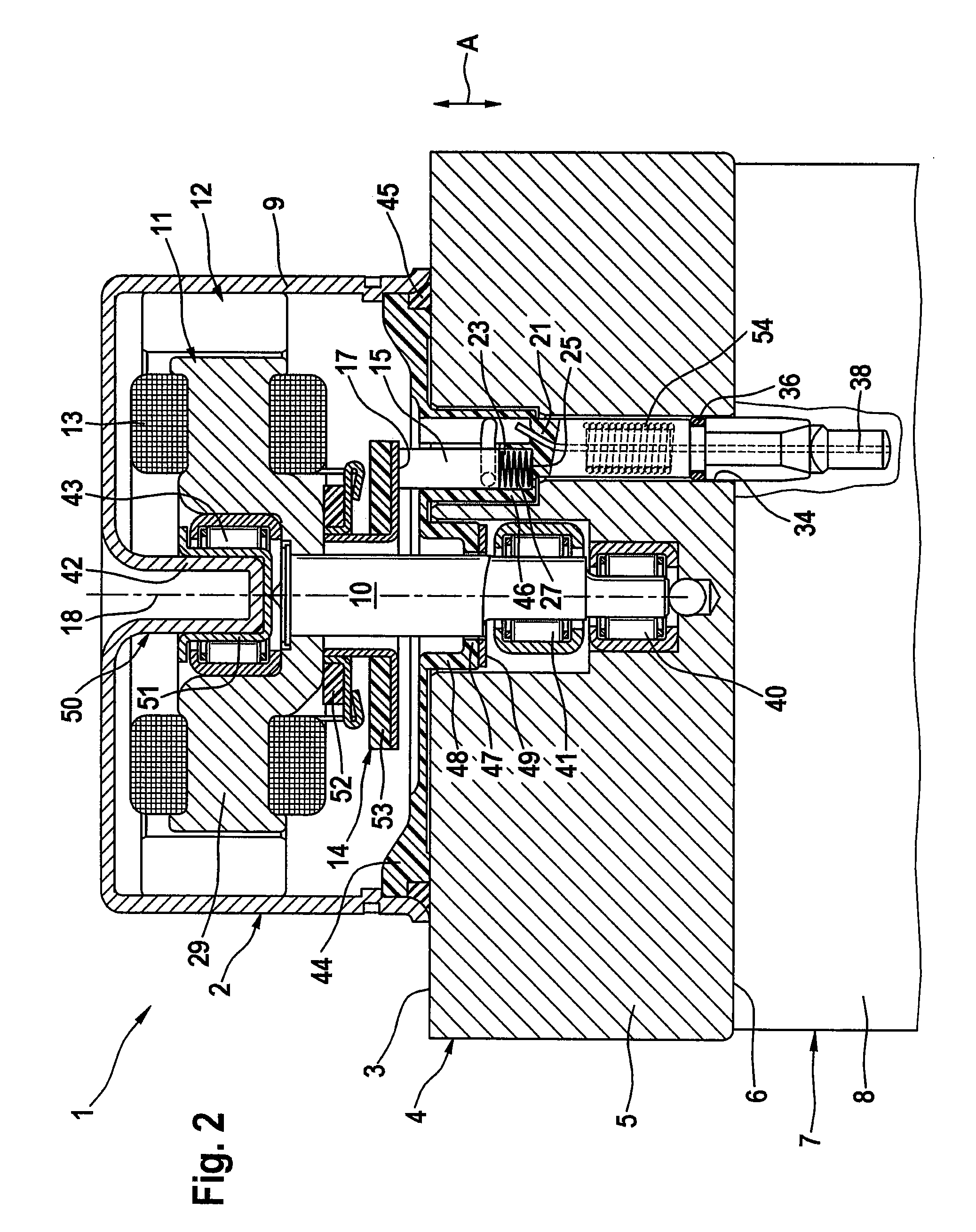
[0033]To begin with, reference is therefore made to FIG. 9 in order to explain principal relationships in electrohydraulic aggregates. The electrohydraulic aggregate 1 serves for the hydraulic energy supply of an anti-lock brake device of a motor vehicle. The aggregate comprises an electric motor 2, which is arranged and fastened at a first side 3 of an accommodating member 4 (HCU) with electrohydraulic valves and with a housing 5 for a piston pump. An electronic unit 7 (ECU) with a housing 8 is arranged and fastened on another side, i.e. the second side 6 of the accommodating member 4. Unit 7 basically serves to actuate solenoid valves (not shown) for the modulation of the brake pressure in brake units as well as for the electric supply of the electric motor 2. The electric motor 2 is equipped with a stator 12 with a pot-shaped motor housing 9 comprising magnets and a rotor 11 with a shaft 10. Spaced bearings are used for the mounting support of the rotor, and it has become general...


PUM


Abstract

An electrohydraulic aggregate for converting electric energy into mechanical energy, comprising an electric motor with a stator and with a rotor, comprising magnets or electric windings that produce electromagnetic fields, at least one connecting component for connecting the windings to at least one energy supply, with the connecting component extending through at least one through-hole, the through-hole is provided in an accommodating member accommodating electrohydraulic valves as well as at least one piston pump for the energy supply of a slip-controlled brake system, the piston pump being connected to the electric motor by a gear, and a rotor mounting support comprising at least two spaced rotor bearings, of which at least one so-called A-bearing supports a shaft in the accommodating member, and a so-called B-bearing that is supported in a pot-shaped motor housing.

Description

[0001]This application is the U.S. national phase application of PCT International Application No. PCT / EP2006 / 062276, filed May 12, 2006, which claims priority to German Patent Application No. DE102005023039.3, filed May 13, 2005 and German Patent Application No. DE102005035834.9, filed Jul. 30, 2005, the contents of such applications being incorporated by reference herein.BACKGROUND OF THE INVENTION[0002]1. Field of the Invention[0003]The present invention relates to an electrohydraulic aggregate in a compact type of construction comprising a housing, a rotor, and a stator with electric windings, wherein a commutator-carbon brush system is provided in order to feed the electric windings with current depending on the rotary position of the rotor, and wherein the stator embraces the rotor, that comprises a shaft and permanent magnets, for mounting on an accommodating member.[0004]2. Description of the Related Art[0005]DE 100 45 549 A1 discloses an electric motor. For the reduction of...

Claims


Application Information

Patent Timeline
IPC IPC(8): H02K5/16H01R39/26
CPCB60T8/368B60T8/4022F04B17/03F16C35/06H02K7/086H02K5/148H02K5/225H02K7/075H02K7/083H01R39/38
Inventor DINKEL, DIETERFEIGEL, HANS-JORG
Owner CONTINENTAL TEVES AG & CO OHG
Why Eureka
Try Eureka