
Exhaust Gas Recirculation System

Inactive Publication Date: 2008-07-31
HITACHI LTD
View PDF11 Cites 41 Cited by
  • Summary
  • Abstract
  • Description
  • Claims
  • Application Information

AI Technical Summary

Benefits of technology

[0009]The present invention has been made in view of the above circumstances. An object of the present invention is to provide a technique for preventing the EGR flow rate detection accuracy of an EGR sensor installed in an EGR path of an engine from being decreased due to a soiling substances entry into the EGR path.
[0011]Still another object of the present invention is to prevent an EGR system from operating in accordance with a wrong signal of the EGR sensor.
[0012]To achieve at least one of the above objects, the present invention includes a catalyst for purifying the EGR gas or exhaust. The catalyst is positioned upstream of the EGR sensor, which detects the amount of EGR in the EGR path. While the catalyst is active, the present invention can prevent the EGR sensor from being soiled because the catalyst purifies soiling substances contained in the EGR gas or exhaust.
[0013]Another aspect of the present invention properly controls the status of the EGR system in accordance with the conditions of the catalyst. In this case, it is preferred that the EGR sensor have a flow rate measurement mode and a soilure protection mode. Specifically, while the catalyst is inactive, control is exercised to place the EGR sensor in the soilure protection mode in which the sensor protects itself against flowing soiling substances (e.g., in an output stop state or in a heating state in which a heater burns soiling substances away). While the catalyst is active, on the other hand, control is exercised to place the EGR sensor in the flow rate measurement mode. Consequently, the EGR sensor is less likely to be affected by soiling substances in the exhaust under any circumstances of the EGR path. Since this prevents the accuracy of EGR gas detection from decreasing, it is possible to prevent the deterioration of engine combustion state and exhaust.
[0014]The present invention, which has been described above, includes a catalyst that is installed upstream of the EGR sensor to purify soiling substances in the EGR gas. This allows the EGR sensor to substantially avert the influence of soiling substances in the exhaust and to avoid a decrease in the accuracy of EGR gas flow rate detection. As a result, it is possible to avoid the deterioration of engine combustion state and exhaust.

Problems solved by technology

However, the techniques described above entail the following problems.
Further, if carbon or other substances are deposited in the EGR path in the case where the EGR sensor calculates a flow rate from the flow velocity of EGR gas, the inside diameter of the pipe decreases, leading to the problem that the EGR flow rate cannot be accurately calculated from the flow velocity.

Method used


Image

  • Exhaust Gas Recirculation System
  • Exhaust Gas Recirculation System
  • Exhaust Gas Recirculation System

Examples


first embodiment

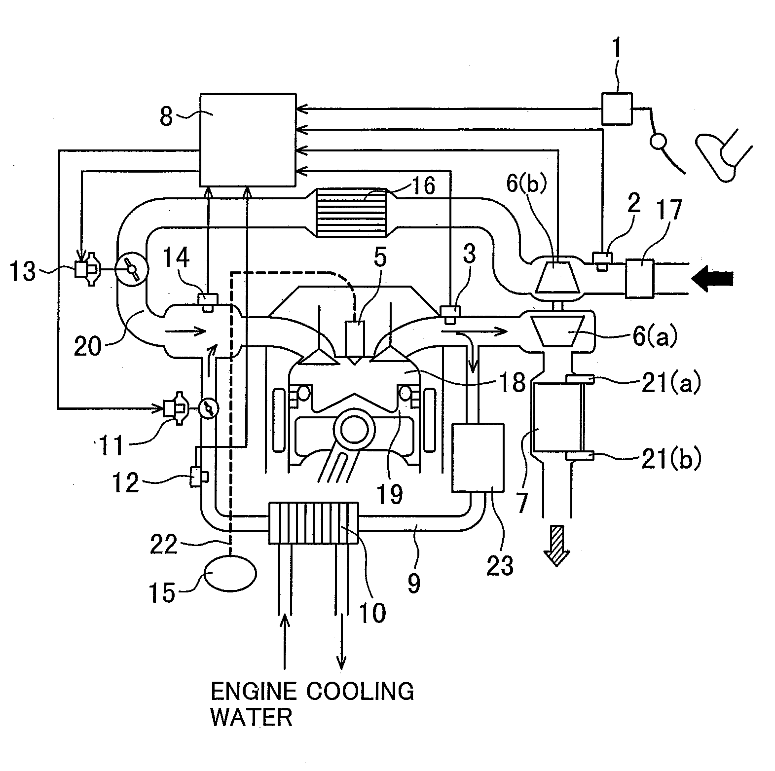
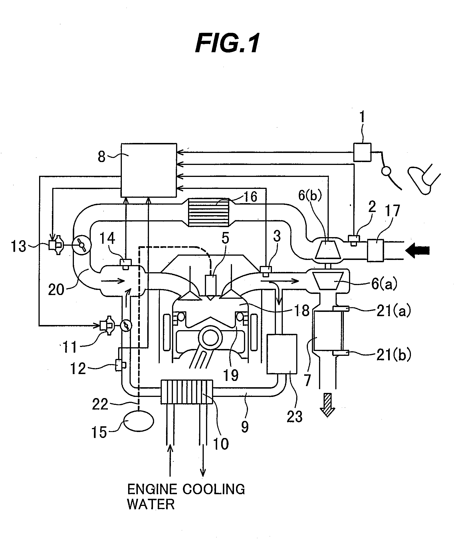
[0030]FIG. 1 shows the configuration of an engine according to the present invention. In FIG. 1, the reference numeral 19 denotes the engine. Positioned upstream of the engine 19 are an air cleaner 17; an air flow sensor 2; a compressor 6(b) for a supercharger; an intercooler 16; a throttle valve 13 for intake air amount adjustment; an intake path 20; and a fuel injection valve (hereinafter referred to as the injector) 5. Intake air amount control means according to the present embodiment is composed of the compressor 6(b), intercooler 16, and throttle valve 13, whereas intake air amount detection means is the air flow sensor 2. The injector 5 is designed to directly inject fuel into a combustion chamber 18. It is preferred that the throttle valve 13 be electronically controlled. The throttle valve 13 of the present embodiment is driven by an electric actuator. In the present embodiment, the intake path 20 is provided with an intake pressure sensor 14, which detects the pressure wit...

fourth embodiment

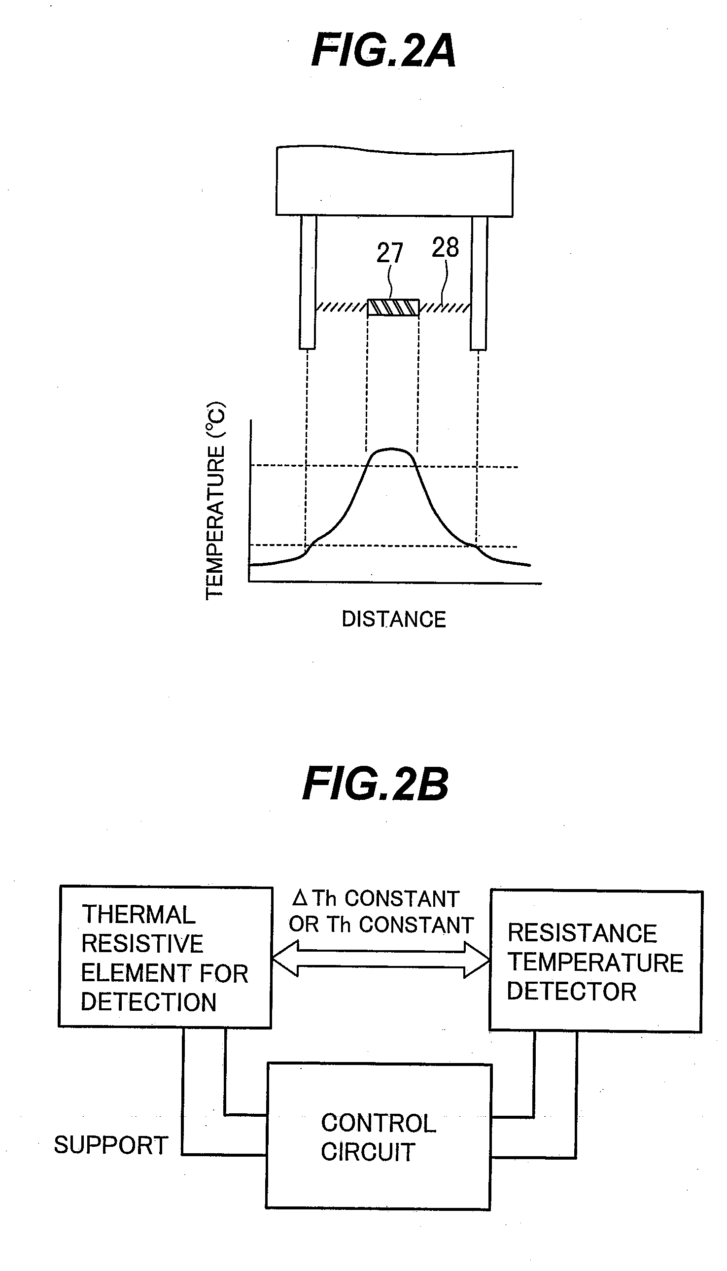
[0053]FIG. 12 is a typical diagram illustrating a situation where the protection mode of the EGR sensor is used in accordance with the Line L7 in the diagram represents the surface temperature of the hot wire 27. Line L8 represents a status flag of the EGR flow sensor 12, which is to be judged by the ECU 8. Line L9 represents the temperature of the EGR catalyst 23. First of all, when the engine starts up, the temperature of the exhaust catalyst 7 is low such that the purification catalyst is inactive (light-off is not completed). Thus, soiling substances in the engine exhaust cannot be purified. Such being the case, the EGR flow sensor 12 enters the soilure protection mode to raise the temperature of the hot wire 27 preferably to 600° C. or higher, as indicated by lines L7 and L8. This makes it possible to burn soiling substances attached to the surface of the hot wire 27 and to avoid the attachment of soiling substances during the soilure protection mode. Subsequently, after the e...


PUM


Abstract

The present invention prevents an EGR sensor installed in an engine's EGR path from being soiled by soiling substances in exhaust. A catalyst is positioned upstream of the EGR sensor to purify the soiling substances in EGR gas. The status of the EGR sensor is properly controlled in accordance with the conditions of the catalyst. This ensures the EGR sensor is less likely to be affected by the soiling substances in the exhaust under any circumstances of the EGR path and allows the EGR sensor to avoid a decrease in the accuracy of EGR gas detection. An alternative configuration may be employed such that the EGR gas recirculates from the downstream side of a catalyst installed in a main exhaust path.

Description

BACKGROUND OF THE INVENTION[0001]1. Field of the Invention[0002]The present invention relates to an exhaust gas recirculation (EGR) system for an internal combustion engine and more particularly to a technique for furnishing an EGR path with an EGR sensor for detecting the amount of EGR.[0003]2. Description of the Related Art[0004]There is a known technique for precisely controlling an exhaust gas recirculation rate (EGR rate) in a cylinder of a diesel engine or other lean burn engines and reducing soot and NOx (nitrogen oxide) emissions from the engine in accordance, for instance, with engine operating conditions.[0005]The technique for furnishing an EGR path with an EGR sensor for EGR flow rate detection for the purpose of precise detection or control of an EGR flow rate is disclosed, for instance, by JP-A-2006-214275, JP-A-2005-140024, and JP-A-2006-316706.[0006]Further, a technique for furnishing the upstream side of an EGR cooler installed in an EGR path with a catalyst and tra...

Claims


Application Information

Patent Timeline
IPC IPC(8): F01N11/00F02M25/07F02D21/08F01N3/18
CPCF02B29/0406F02B2275/14F02D41/005F02D2041/0075F02M25/0702Y02T10/47F02M25/0709F02M25/0731F02M25/074F02M25/0754F02M25/0707F02M26/05F02M26/06F02M26/28F02M26/35F02M26/47F02M26/49Y02T10/40
Inventor YAMAOKA, SHIROOHATA, EIICHIROKUBO, JUNTOKUYASU, NOBORUOTSUKI, TOSHIKIHOSHIKA, HIROAKI
Owner HITACHI LTD
Learn More