
Terahertz camera

a liquid crystal imaging and terahertz radiation technology, applied in the field of radiometry, can solve the problems of lack of sensitivity of the detector to non-visible radiation, limited range of lenses, and high price of infra-red lenses

Inactive Publication Date: 2008-07-31
RADIABEAM TECH
View PDF42 Cites 18 Cited by
  • Summary
  • Abstract
  • Description
  • Claims
  • Application Information

AI Technical Summary

Benefits of technology

[0007]The reflected color distribution for most TLC materials varies continuously from the longer wavelengths (red) at the event temperature to shorter wavelengths (blue) at the clearing point temperature. Because a TLC material also transmits a significant amount of the incident light with virtually no modification, TLCs may be viewed against a nonreflecting (black) background to prevent this unimportant light from adversely affecting the interpretation of the selectively reflected light. The color-temperature response may be captured with a color camera and a color-versus-temperature calibration curve may be used to create a very effective TLC-based thermography system.
[0011]In a final embodiment of the invention, a method for adjusting the temperature of a thermochromic liquid crystal layer used for converting a thermal image into a visible image is described. The method includes transmitting infrared radiation onto the thermochromic liquid crystal layer such that a visible image appears on the layer. Then, the step of capturing the visible image on a digital camera, feeding the image to a computer, and, by using the computer, translating the image into a two dimensional map of the temperature of the thermochromic liquid crystal. The computer analyzes the image and determining whether the image is saturated, lowering the temperature of the thermochromic liquid crystal layer if the image is saturated; and otherwise maintaining the temperature of the thermochromic liquid crystal layer at a central temperature if the image is not saturated. In this way, the thermochromic liquid crystal may be held to an optimal temperature for color sensitivity.

Problems solved by technology

Infra-red lenses are expensive, and infra-red zoom lenses particularly so; so for any individual system, the range of lenses is usually limited.
The lack of sensitivity of the detector to non-visible radiation is still a problem that confronts the art.

Method used


Image

  • Terahertz camera
  • Terahertz camera

Examples


Embodiment Construction

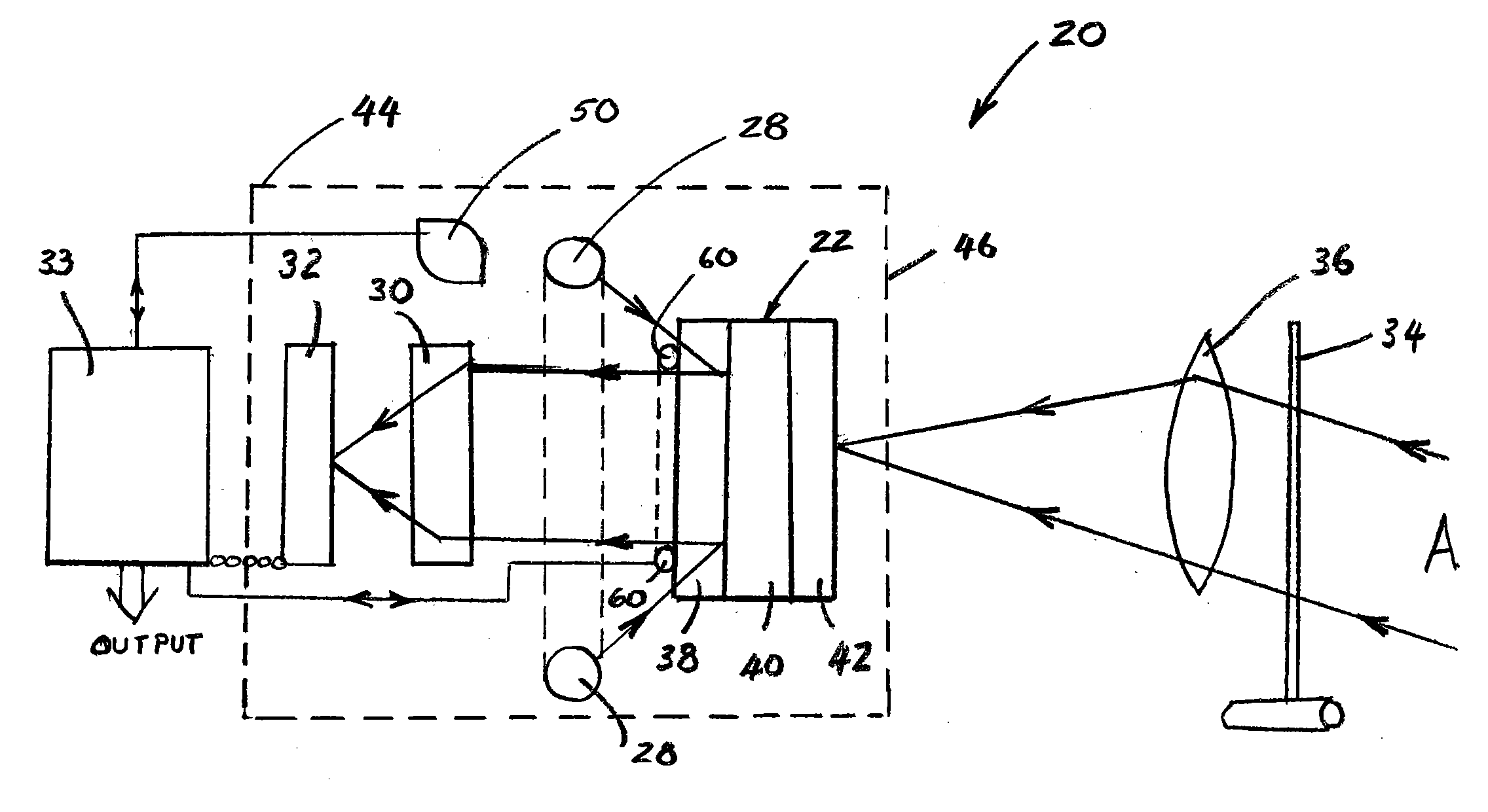
[0015]With reference to the figures, a preferred embodiment of the invention includes a thermal imaging device 20 for detecting the presence of electromagnetic waves in the terahertz frequency range, and converting such waves to a storable image in the visible frequency range.

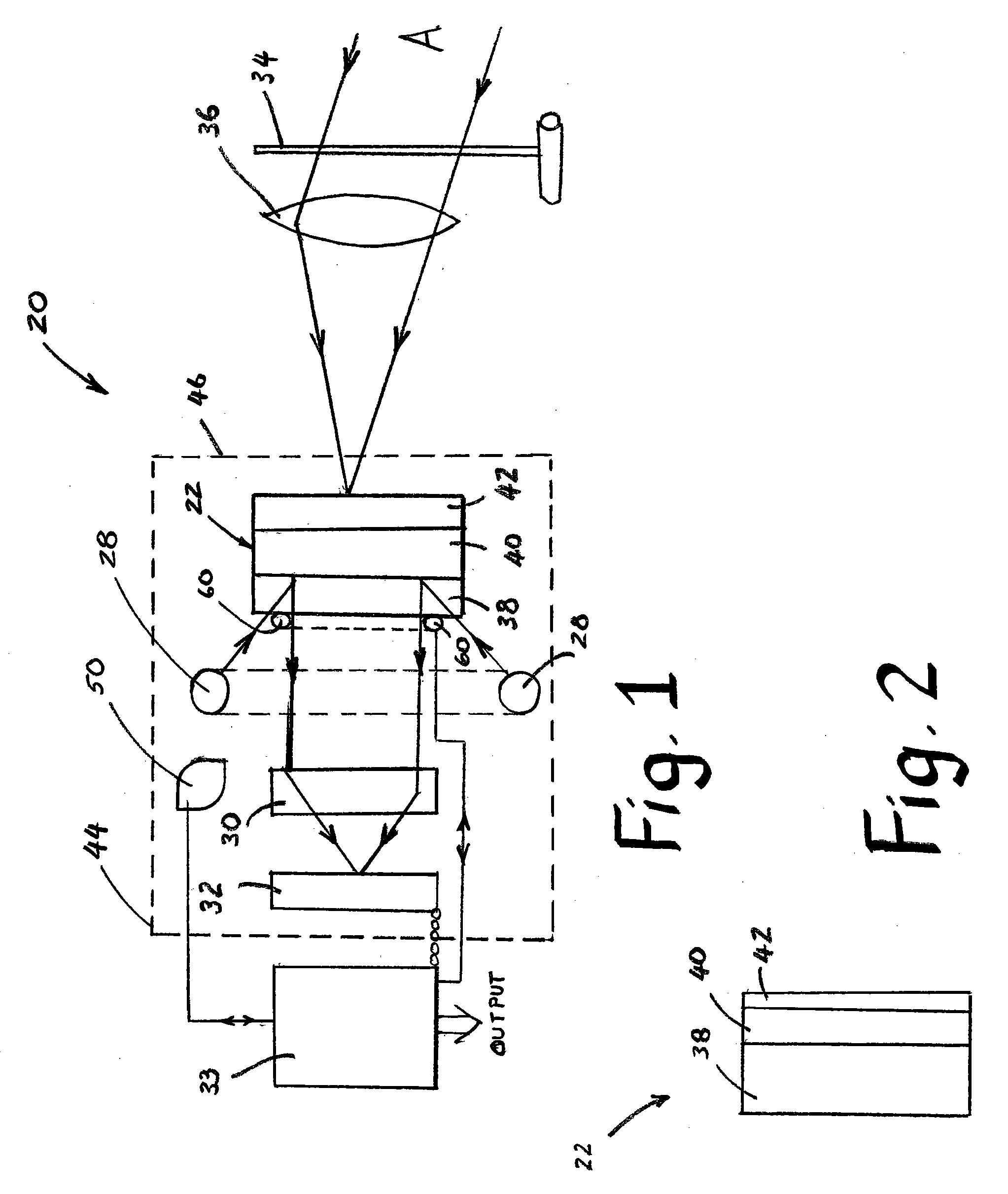
[0016]Referring first to FIG. 1, the device 20 includes a converter 22 having a forward face and a rearward face. The terms “forward” and “rearward” are defined in relation to the orientation of the thermal imaging device, with forward being the direction of the object to be imaged. A means for forming a focused image of a thermal scene on to the forward face of the converter 22 may be provided, but is not a requirement of the invention. In an alternative embodiment, there may be provided an aperture (not shown) of suitable dimension to focus the electromagnetic waves by the well known pinhole effect. The aperture may be sealed by a transparent material having no optical properties. Focusing the incoming electr...


PUM

PropertyMeasurementUnit
aspect ratioaaaaaaaaaa
thicknessaaaaaaaaaa

Abstract

A thermal imaging device is provided for converting an image in the terahertz radiation range to the visible range. In one embodiment, the device includes a converter having a thermochromic liquid crystal layer mounted on a sapphire base. In another embodiment, the device includes a thermal absorption layer including a metal selected from the group of iron, aluminum, tin, and copper. In a further embodiment, the device has an light source shaped as an annulus for illuminating a rearward surface of the converter, configured to permit visible light rays to pass through the annulus for capture by a digital detector. In a final embodiment, the device has a thermal adjustment device for adjusting the temperature of the thermochromic liquid crystal layer to an optimal temperature.

Description

BACKGROUND OF THE INVENTION[0001]The present invention relates to radiometry and, more particularly, to a terahertz radiation liquid crystal imaging system.[0002]Over the past 30 years, thermochromic liquid crystal (TLC)-based thermography systems have provided engineers with a relatively inexpensive technique for investigating thermal phenomena in the electronics, automotive, and aerospace industries, as well as in academia.[0003]Conventional TLC thermal imaging devices include an infra-red sensitive detector and one or more infra-red optical components which focus the radiation from a thermal scene on to the surface of the detector, which operates to convert the infra-red radiation into visible radiation. The material of the detector (converter) is chosen to have a highly temperature-dependent optical property, such as birefringence or optical rotation. This detector is also illuminated by a visible or near-visible polarized light source the output of which is reflected onto the d...

Claims


Application Information

Patent Timeline
Patent Type & Authority Applications(United States)
IPC IPC(8): G02F1/13
CPCG02F2203/13G02F1/132
Inventor ANDONIAN, GERALDBOUCHER, SALIME M.FRIGOLA, PEDRO E.MUROKH, ALEX Y.SHAFTAN, TIMURTRAVISH, GIL
Owner RADIABEAM TECH
Features
  • Generate Ideas
  • Intellectual Property
  • Life Sciences
  • Materials
  • Tech Scout
  • Unparalleled Data Quality
  • Higher Quality Content
  • 60% Fewer Hallucinations
Learn More