Motor drive system for railway vehicle

a technology for railway vehicles and motors, applied in the direction of motor/generator/converter stoppers, multiple dynamo-motor starters, electric devices, etc., can solve the problems of limited arranging of inverters as close to the motor, malfunction of railway signals, and general bulkyness, and achieve low capacity, suppress current ripple, and reduce the effect of vibration

Active Publication Date: 2008-07-31
KK TOSHIBA
View PDF20 Cites 14 Cited by
  • Summary
  • Abstract
  • Description
  • Claims
  • Application Information

AI Technical Summary

Benefits of technology

[0009]An object of the present invention is to provide a motor drive system for a railway vehicle, capable of reducing the weight of wiring, electromagnetic noise, and manufacturing cost.
[0015]According to a sixth aspect of the present invention, the motor is a permanent-magnet motor having a sealed area inside a frame of the motor, and components of the inverter are arranged in the sealed area, to eliminate a switch for electrically disconnecting the inverter from the motor.
[0016]The inverter in the motor drive system for a railway vehicle according to the present invention employs switching elements of low withstand voltage. The low-withstand-voltage switching elements are mass-produced for, for example, hybrid electric cars and are inexpensive. The present invention arranges at least two such inverters to form a multiphase circuit that compensates for the low withstand voltage and low capacity and suppresses a current ripple. The present invention integrates the inverters with the motor, to reduce the weight of wiring, electromagnetic noise, and manufacturing cost.

Problems solved by technology

The current harmonics passed through long wiring cause electromagnetic noise that may cause malfunctions of railway signals.
The inverter, however, is generally bulky, and therefore, there are limits on arranging the inverter as close to the motor as possible to shorten the wiring.
Semiconductor switching elements of high withstand voltage used for railway inverters are special-purpose products that are costly to manufacture.

Method used


Image

  • Motor drive system for railway vehicle
  • Motor drive system for railway vehicle
  • Motor drive system for railway vehicle

Examples


first embodiment

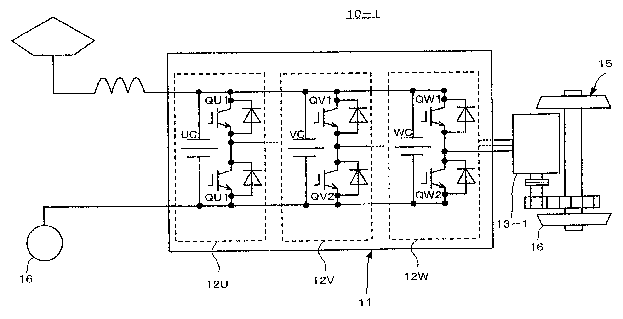
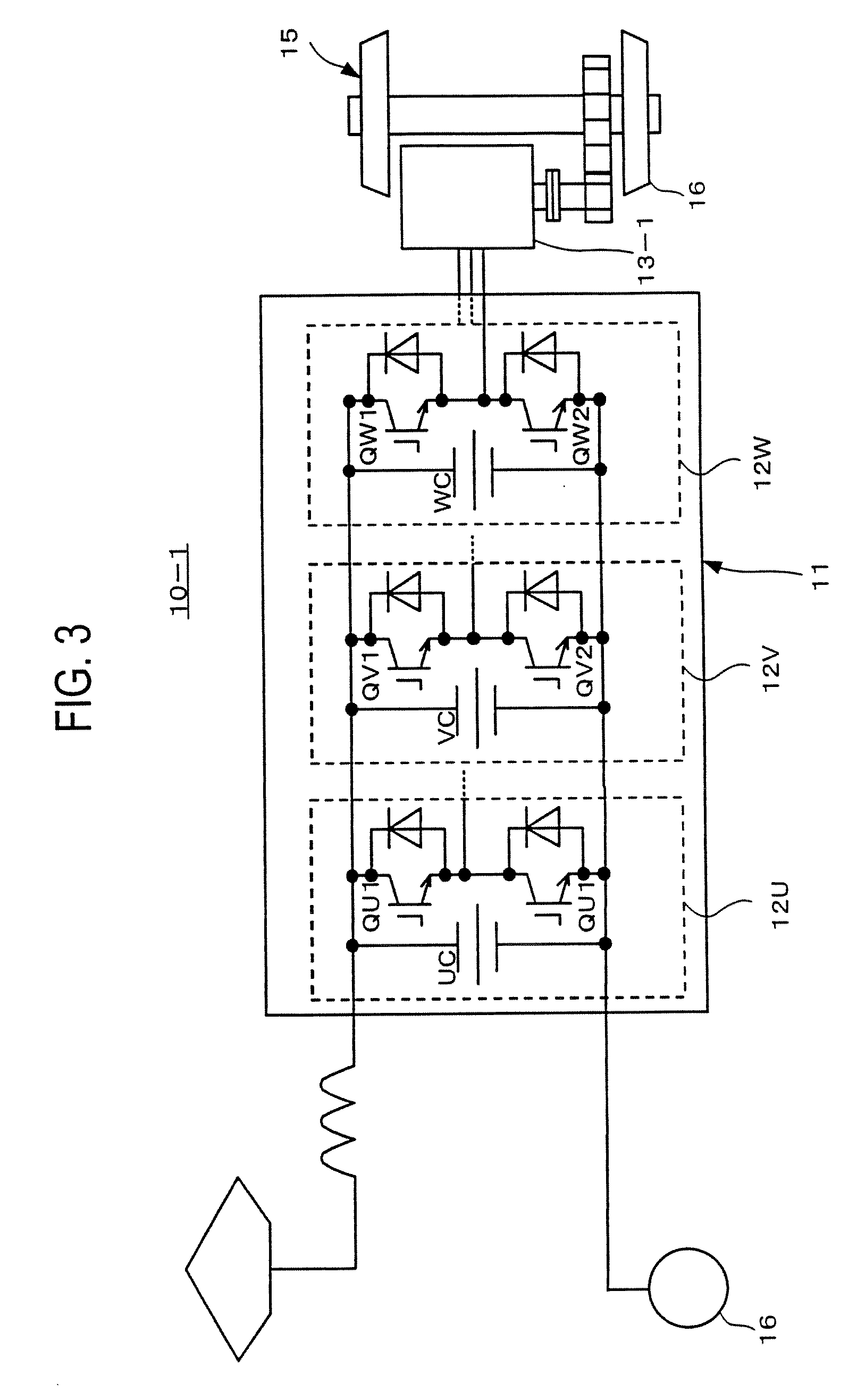
[0031]A motor drive system for a railway vehicle according to the first embodiment of the present invention will be explained with reference to FIGS. 3 to 5. The motor drive system 10-1 according to the first embodiment includes a three-phase inverter 11 and a three-phase, permanent-magnet synchronous motor 13-1. The inverter 11 includes a U-phase unit 12U having two pairs of U-phase switching elements, a V-phase unit 12V having two pairs of V-phase switching elements, and a W-phase unit 12W having two pairs of W-phase switching elements.

[0032]The U-phase unit 12U has two IGBTs (Insulated Gate Bipolar Transistors) QU1 and QU2 and a capacitor UC and forms an arm of the two-level inverter 11. Each of the V- and W-phase units 12V and 12W is similarly formed.

[0033]As shown in detail in FIG. 5, the U-, V-, and W-phase units 12U, 12V, and 12W are mechanically separated from one another and are arranged on the surface of the motor 13-1. As shown in detail in FIG. 3, direct-current parts of...

second embodiment

[0036]A motor drive system for a railway vehicle according to the second embodiment of the present invention will be explained with reference to FIGS. 6 and 7. The motor drive system 10-2 of the second embodiment includes a first inverter 11-1, a second inverter 11-2, a third inverter 11-3, and a three-phase, three-winding, permanent-magnet synchronous motor 13-2.

[0037]As shown in FIG. 6, the first inverter 11-1 is a two-level, full-bridge inverter having six IGBT switching elements and a capacitor. Generally, railway vehicles employ a DC voltage of 1500 V, and therefore, IGBTs each having a withstand voltage of 3300 V are usually adopted. On the contrary, the six IGBT switching elements employed by the second embodiment for each inverter are each of a withstand voltage of 1200 V. The IGBT switching elements of 1200-volt withstand voltage are widely available for, for example, hybrid electric cars, and therefore, are inexpensive. The second and third inverters 11-2 and 11-3 are cons...

third embodiment

[0041]A motor drive system for a railway vehicle according to the third embodiment of the present invention will be explained with reference to FIGS. 8 to 11.

[0042]As shown in detail in FIG. 8, the motor drive system 10-3 of the third embodiment includes a first inverter 11A, a second inverter 11B, and a six-phase, permanent-magnet synchronous motor 13-3. The first inverter 11A is a two-level, full-bridge inverter having six IGBT switching elements and a capacitor. The second inverter 11B is constituted like the first inverter 11A. Direct-current ends of the first and second inverters 11A and 11B are connected in parallel, to receive a voltage from an overhead line.

[0043]As shown in detail in FIG. 9, the first and second inverters 11A and 11B are mechanically separated from each other and are arranged on the surface of the motor 13-3. Alternating-current output ends of each of the inverters 11A and 11B are connected to phase input terminals of the motor 13-3. The integrated structur...


PUM


Abstract

A motor drive system 10-1 for a railway vehicle is capable of reducing the weight of wiring, electromagnetic noise, and manufacturing cost. The motor drive system includes an inverter 11. The inverter is configured to control a motor 13-1 and is divided into at least two separate inverter units that are arranged integrally with the motor.

Description

CROSS REFERENCE TO RELATED APPLICATION[0001]The present application claims the benefit of priority under 35 U.S.C. § 119 to Japanese Patent Application No. 2007-015254, filed on Jan. 25, 2007, the entire contents of which are incorporated herein by reference.BACKGROUND OF THE INVENTION[0002]1. Field of the Invention[0003]The present invention relates to a motor drive system for a railway vehicle.[0004]2. Description of Related Art[0005]Examples of motor drive systems for railway vehicles are disclosed in Japanese Unexamined Patent Application Publication No. 2000-308388, Japanese Patent Publication No. 3594100, and the like. FIG. 1 is a circuit diagram showing a motor drive system 100 for a railway vehicle according to a related art. FIG. 2 shows an inverter 110 of the motor drive system 100, wheels 120, a motor 130, and the like arranged in the railway vehicle of FIG. 1.[0006]To make the motor 130 free of maintenance, the motor drive system 100 of the related art employs, as the mo...

Claims


Application Information

Patent Timeline
Patent Type & Authority Applications(United States)
IPC IPC(8): H02K19/10H02K21/02
CPCB60L9/005B60L9/32B60L2210/46B60L2220/58B60L2200/26H02M2001/0074H02P25/22Y02T10/641Y02T10/7241H02K11/0073H02K11/33Y02T10/64Y02T10/72H02M1/0074
Inventor NAKAZAWA, YOSUKENODA, SHINICHIYUUKI, KAZUAKIFUKUDA, KAZUAKI
Owner KK TOSHIBA
Why Eureka
Try Eureka