Modular and reconfigurable multi-stage high temperature microreactor cartridge apparatus and system for using same

a high-temperature microreactor and cartridge technology, applied in the field of microfluidic chemical reactions and analyses, can solve the problems of slow commercial success development, difficult conditions for diverse chemical reactions, clogging of systems, etc., and achieve the effects of improving efficiency, consuming small amounts of starting materials, and high speed

Inactive Publication Date: 2008-07-31
ADVION
View PDF56 Cites 33 Cited by
  • Summary
  • Abstract
  • Description
  • Claims
  • Application Information

AI Technical Summary

Benefits of technology

[0003]Microfluidics has long been used to manipulate fluids in channels with height and width that typically range from 1 to 500 micrometers. Fluids are moved in volumes of nanoliters or microliters. “Lab-on-a-chip” technology has used microfluidics to perform chemical reactions and analyses at very high speeds while consuming small amounts of starting materials. Various chemical reactions require difficult conditions such as high pressure and high temperatures. Microfluidic systems use miniaturized reactors, mixers, heat exchangers, and other processing elements for performing chemical reactions on a miniature scale. Such systems are useful for reactions such as pharmaceutical or laboratory reactions where very small and accurate amounts of chemicals are necessary to successfully arrive at a desired product. Furthermore, use of microfluidic systems increases efficiency by reducing diffusion times and the need for excess reagents.

Problems solved by technology

Various chemical reactions require difficult conditions such as high pressure and high temperatures.
Applications for microfluidic systems are generally broad, but commercial success has been slow to develop in part because microfluidic devices are difficult and costly to produce.
Other considerable problems include clogging of the systems, fouling of the reagent in the system, and supplying new reagent once the previous supply is depleted, clogged, or fouled.
Furthermore, waste accumulations and air bubbles interfere with proper microfluidic system operation.
Also, some reaction applications require extremely high temperature reactors, which have previously been unavailable in micro- and nanoscale devices.

Method used


Image

  • Modular and reconfigurable multi-stage high temperature microreactor cartridge apparatus and system for using same
  • Modular and reconfigurable multi-stage high temperature microreactor cartridge apparatus and system for using same
  • Modular and reconfigurable multi-stage high temperature microreactor cartridge apparatus and system for using same

Examples


Embodiment Construction

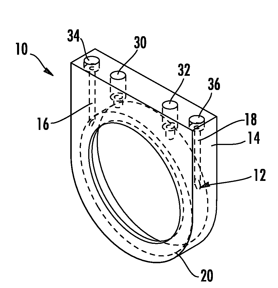
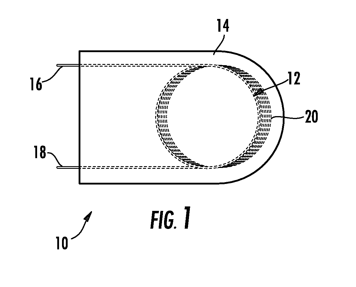
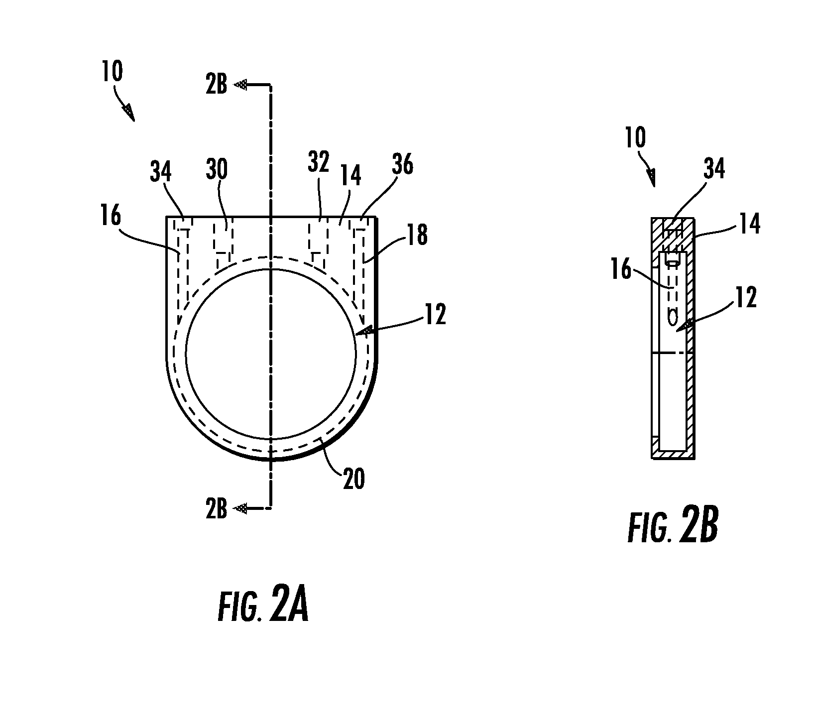
[0015]Referring to FIG. 1A, a microfluidic reactor cartridge 10 is shown. The cartridge has a coil of capillary tubing 12 having a first transport portion 16, a spool portion 20, and a second transport portion 18. The coil 12 is surrounded by a housing 14 capable of withstanding high temperatures and the housing 14 functions in part as an external spool for holding, protecting and heating the spool portion 20 of the tubing 12. In one embodiment the coil 12 is made of glass, and the housing 14 is made of high temperature materials. For example, appropriate materials for the housing are: nickel, quartz glass, and ceramic. The microfluidic reactor cartridge 10 may be used as a high temperature gas reactor, such as below regarding the method for making methyl iodide (FIG. 4). The coil 12 is small bore capillary tubing in the range of 1 to 2500 micrometers in diameter and a maximum length of several meters. Further, a cross-section of the capillary tubing may be any shape, but preferably...


PUM


Abstract

A microfluidic reactor cartridge having glass capillary tubing wound in a coil and surrounded by a ceramic housing capable use in high temperatures and method for using same. In another embodiment, the microfluidic cartridge is a serpentine reactor cartridge with a serpentine microreactor channel formed in a ceramic housing. The serpentine reactor cartridge has an inlet tube attached to its inlet port and an outlet tube attached to its outlet port. The inlet port is a macro / micro interface and the outlet port is a micro / macro interface useful in gas phase reactions where solids must be used to produce a reactant. The method for using a microfluidic reactor cartridge includes two phases, the first phase for producing a radioactive labeled gas such as methyl iodide and the second phase is a methylation reaction.

Description

CROSS REFERENCE TO RELATED APPLICATION[0001]This patent application claims priority from and is related to U.S. Provisional Patent Application Ser. No. 60 / 823,303 filed Aug. 23, 2006, entitled: “Modular and Reconfigurable Multi-Stage High Temperature Microreactor Cartridge Apparatus and System for Using Same”. This U.S. Provisional Patent Application is incorporated by reference in its entirety herein.FIELD[0002]This invention relates to the field of microfluidic chemical reactions and analyses of the same. More particularly, this invention relates to a modular and reconfigurable multi-stage high temperature microreactor cartridge apparatus and system for using the same.BACKGROUND AND SUMMARY[0003]Microfluidics has long been used to manipulate fluids in channels with height and width that typically range from 1 to 500 micrometers. Fluids are moved in volumes of nanoliters or microliters. “Lab-on-a-chip” technology has used microfluidics to perform chemical reactions and analyses at ...

Claims


Application Information

Patent Timeline
Patent Type & Authority Applications(United States)
IPC IPC(8): B01J19/02
CPCB01J19/0093B01J2219/00783B01J2219/00788B01J2219/0081B01J2219/00822B01J2219/00909B01J2219/00826B01J2219/00831B01J2219/0086B01J2219/00871B01J2219/00891B01J2219/00824
Inventor MATTEO, JOSEPH C.
Owner ADVION
Why Eureka
Try Eureka