Micro fuel cell having macroporous metal current collectors

a fuel cell and micro-porous technology, applied in the field of micro-porous metal current collectors, can solve the problems of limited energy stored in batteries, inconvenience of batteries, limited amount of stored energy,

Inactive Publication Date: 2008-07-31
MOTOROLA INC
View PDF10 Cites 26 Cited by
  • Summary
  • Abstract
  • Description
  • Claims
  • Application Information

AI Technical Summary

Problems solved by technology

The energy stored in the batteries is limited.
The limited amount of stored energy and the frequent recharging are major inconveniences associated with batteries.
However, the energy generated by these methods is small, usually only a few milliwatts.
In the regime of interest, namely, a few hundred milliwatts, this dictates that a large volume is required to generate sufficient power, making it unattractive for cell phone type applications.
However, with this approach the power densities are low and there also are safety concerns associated with the radioactive materials.
This is an attractive power source for remote sensor-type applications, but not for cell phone power sources.
Fuel cells with active control systems and those capable of operating at high temperatures are complex systems and are very difficult to miniaturize to the 2-5 cc volume needed for cell phone application.
However, in addition to the miniaturization issues, other concerns include supply of hydrogen for hydrogen fuel cells, lifetime and energy density for passive DMFC and DFAFC, and lifetime, energy density and power density with biofuel cells.
While this mixture of electrocatalyst / carbon support / ionomer achieves a three point contact between fuel, electron conductor, and proton conductor, the number of three point contacts varies widely according to the fabrication method used, and can thereby limit oxygen reduction reaction kinetics and the maximum power available from the fuel cell.
Furthermore, the thickness of the catalyst / carbon support / ionomer is often greater than ten micrometers and contributes to increased iR losses that result in a voltage drop that lowers the power output of the fuel cell.
Fuel and water diffusion through the electrocatalyst layer is poor (permeability of less than 0.1), resulting in mass-transfer limitations which also decrease the power available from the cell.
Most development activities on small fuel cells are attempts to miniaturize traditional fuel cell designs, and the resultant systems are still too big for mobile applications.
Therefore, the traditional planar fuel cell approach will not be able to meet the requirements in a 1-2 cc volume for a fuel cell in the fuel cell / battery hybrid power source for cell phone use.
However, traditional methods of MEA and fuel cell fabrication are not viable for fabricating a micron-sized, 3D fuel cell.
However, for known micro 3-D fuel cell with anodes and cathodes arranged in the same plane of the substrate, the microporous metal limits the amount of water migration.

Method used


Image

  • Micro fuel cell having macroporous metal current collectors
  • Micro fuel cell having macroporous metal current collectors
  • Micro fuel cell having macroporous metal current collectors

Examples


Embodiment Construction

[0021]The following detailed description of the invention is merely exemplary in nature and is not intended to limit the invention or the application and uses of the invention. Furthermore, there is no intention to be bound by any theory presented in the preceding background of the invention or the following detailed description of the invention.

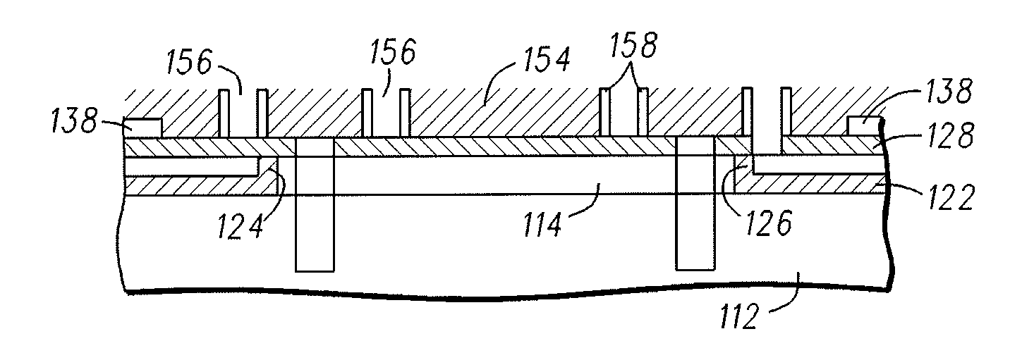
[0022]The main components of a fuel cell device are a proton conducting electrolyte separating the reactant gases of the anode and cathode regions, an electrocatalyst which helps in the oxidation and reduction of the gas species at the anode and cathode of the fuel cell, a gas diffusion layer (GDL) to provide uniform reactant gas access to the anode and cathode and removal of gaseous or liquid by-products from the electrocatalyst, and a current collector for efficient collection and transportation of electrons to a load connected across the fuel cell. In traditional fuel cells, the membrane-electrode assembly comprises a sandwich structure o...


PUM


Abstract

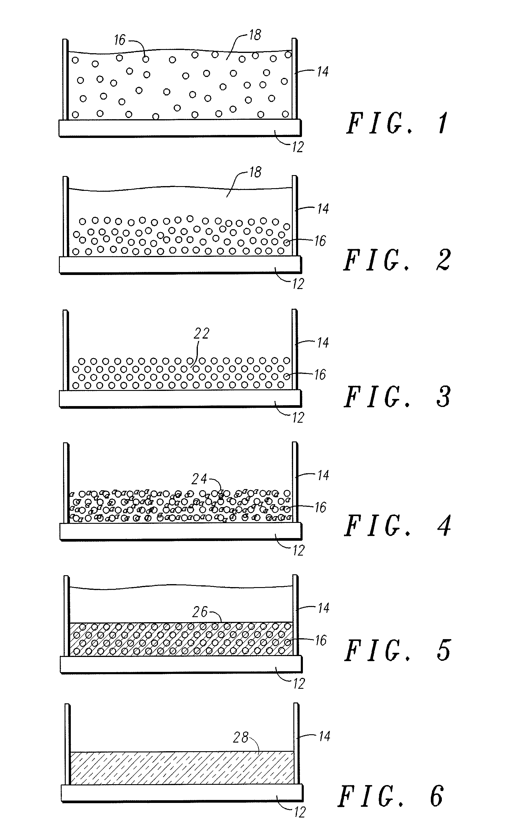
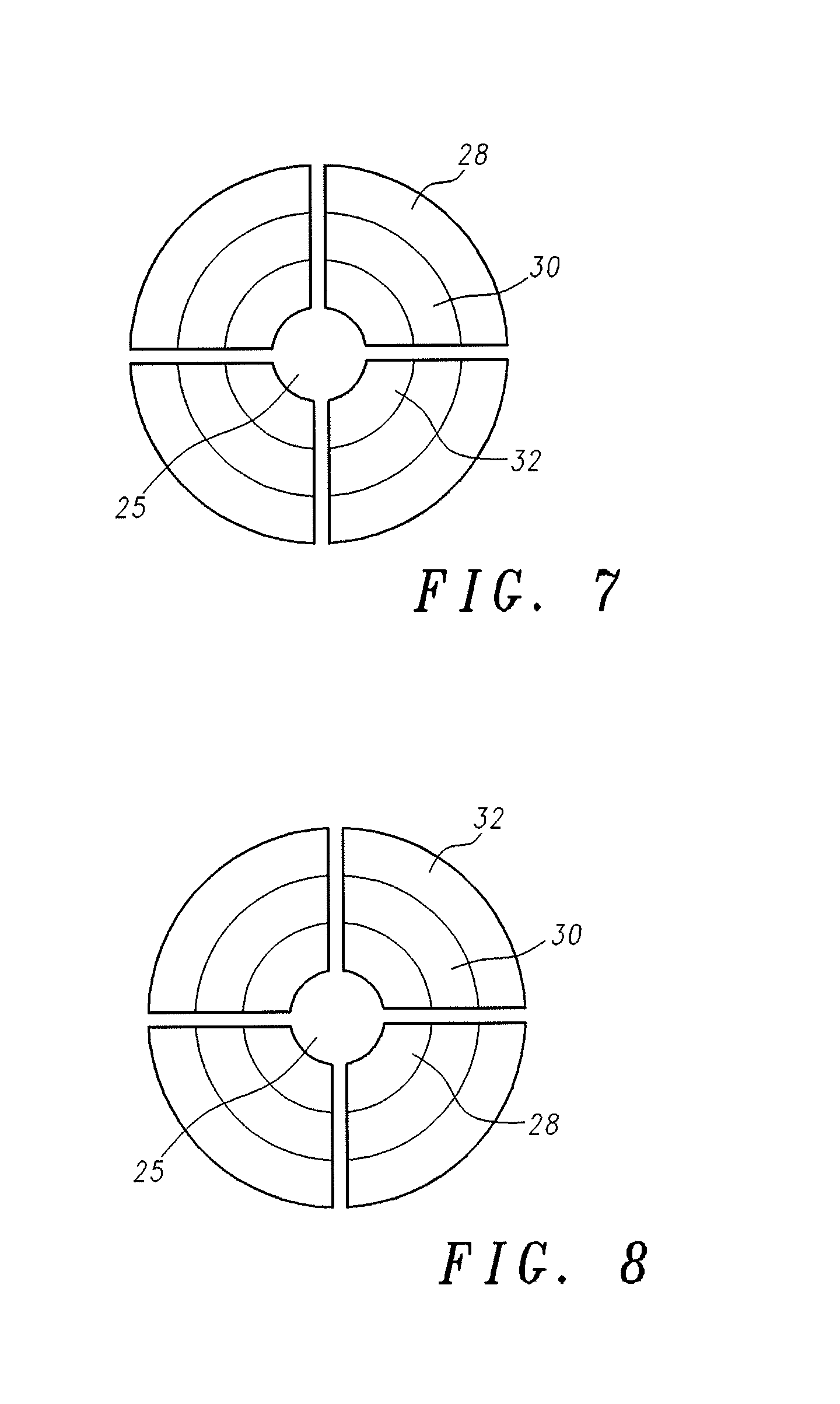
A method is provided for fabricating a hybrid gas diffusion layer / current collector / electrocatalyst structure (28) suitable for 3D microfuel cell devices (180). The method comprises forming a macroporous electrically conductive structure (28) on a substrate (12, 112) positioned such that a plurality of cathode current collector / GDL (168) and anode current collector / GDL (166) are formed. An electrocatalyst material (158) is deposited in contact with these structures, completing the formation of cathode (168) and anode (166) hybrid current collector / GDL / electrocatalyst structures. When electrolyte (158) is positioned between the electrocatalyst material (158) contacting the cathode collector (168) and the electrocatalyst material (158) contacting each of the plurality of anode collectors (166), the resulting MEA is suitable for use in a micro fuel cell device.

Description

RELATED APPLICATIONS[0001]This application relates to U.S. application Ser. No. 11 / 363,790, Integrated Micro Fuel Cell Apparatus, filed 28 Feb. 2006, U.S. application Ser. No. 11 / 479,737, Fuel Cell Having Patterned Solid Proton Conducting Electrolytes, filed 30 Jun. 2006, U.S. application Ser. No. 11 / 519,553, Method for Forming a Micro Fuel Cell, filed 12 Sep. 2006, and U.S. application Ser. No. 11 / 604,035, Method for Forming a Micro Fuel Cell, filed 20 Nov. 2006.FIELD OF THE INVENTION[0002]The present invention generally relates to fuel cells and more particularly to a method of readily providing fuel and oxidant to a micro fuel cell through macroporous current collectors.BACKGROUND OF THE INVENTION[0003]Rechargeable batteries are currently the primary power source for cell phones and various other portable electronic devices. The energy stored in the batteries is limited. It is determined by the energy density (Wh / L) of the storage material, its chemistry, and the volume of the ba...

Claims


Application Information

Patent Timeline
Patent Type & Authority Applications(United States)
IPC IPC(8): B05D5/12
CPCH01M4/8605H01M4/8807H01M4/881H01M4/8853H01M4/8867H01M4/90Y02E60/523H01M8/0234H01M8/0247H01M8/0258H01M8/1004H01M8/1097H01M8/241H01M8/0232H01M8/2418Y02E60/50H01M8/2483
Inventor FISHER, ALLISON M.KRISHNAN, RAMKUMARPAREKH, KAJAL
Owner MOTOROLA INC
Why Eureka
Try Eureka