Strategies for Mitigating Cell Degradation During Start-Up and Shutdown with H2/N2 Storage

Active Publication Date: 2008-07-31
GM GLOBAL TECH OPERATIONS LLC
View PDF6 Cites 25 Cited by
  • Summary
  • Abstract
  • Description
  • Claims
  • Application Information

AI Technical Summary

Benefits of technology

[0016]In accordance with the teachings of the present invention, a system and method are disclosed for reducing cathode carbon corrosion during shutdown and start-up of a fuel cell stack. At system shutdown, the cathode airflow is stopped and the cathode side of the stack is sealed. The flow of hydrogen to the anode side of the stack is continued so that any remaining oxygen in the stack is consumed. The anode side of the stack is sealed so that the flow is only to replace hydrogen that has been pumped to the cathode side of t

Problems solved by technology

This produces a local high potential between the cathode side opposite the air-filled portion of the anode side and adjacent to the electrolyte that drives rapid carbon corrosion, and causes the carbon layer to get thinner.
This decreases the support for the catalyst particles, which decreases the performance of the fuel cell.
Particularly, it is known to pump a mixture of air and a small amount of hydrogen through the cathode side of the stack at system shut-down so that the hydrogen and oxygen combine in the cathode side to reduce the amount of oxygen, and thus the potential that causes the carbon corrosion.
It is also known to short circuit the stack with a resistor at system shut-down to reduce the amount of oxygen on the cathode side of the stack, and thus cathode side corrosion.
This combined electric voltage potential is high enough to severely degrade the catalyst and the carbon particles on which the catalyst is formed, reducing the life of the MEAs in the fuel cell stack.
For example, it has been shown that without addressing the degradation effects of the hydrogen-air front at system start-up, it only takes about 100 shutdown

Method used


Image

  • Strategies for Mitigating Cell Degradation During Start-Up and Shutdown with H2/N2 Storage
  • Strategies for Mitigating Cell Degradation During Start-Up and Shutdown with H2/N2 Storage

Examples


Embodiment Construction

[0020]The following discussion of the embodiments of the invention directed to a system and method for minimizing cathode carbon degradation at system shutdown and start-up is merely exemplary in nature, and is in no way intended to limit the invention or its applications or uses.

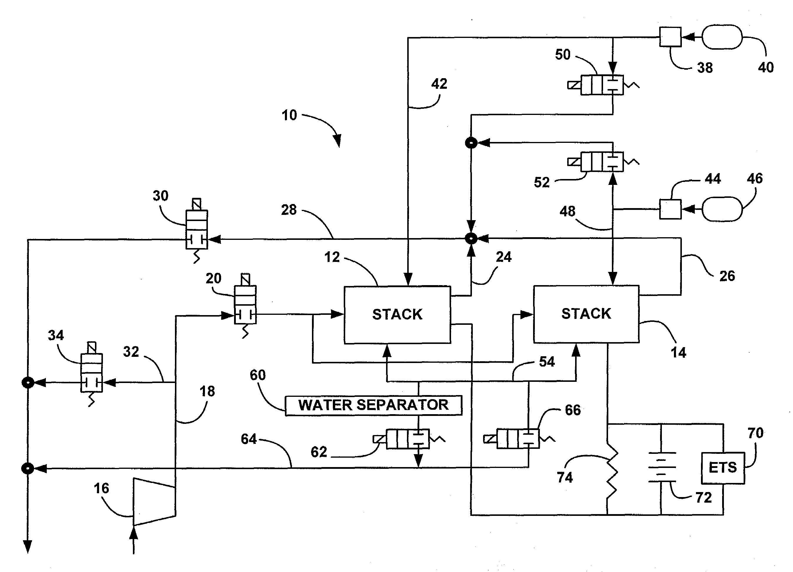
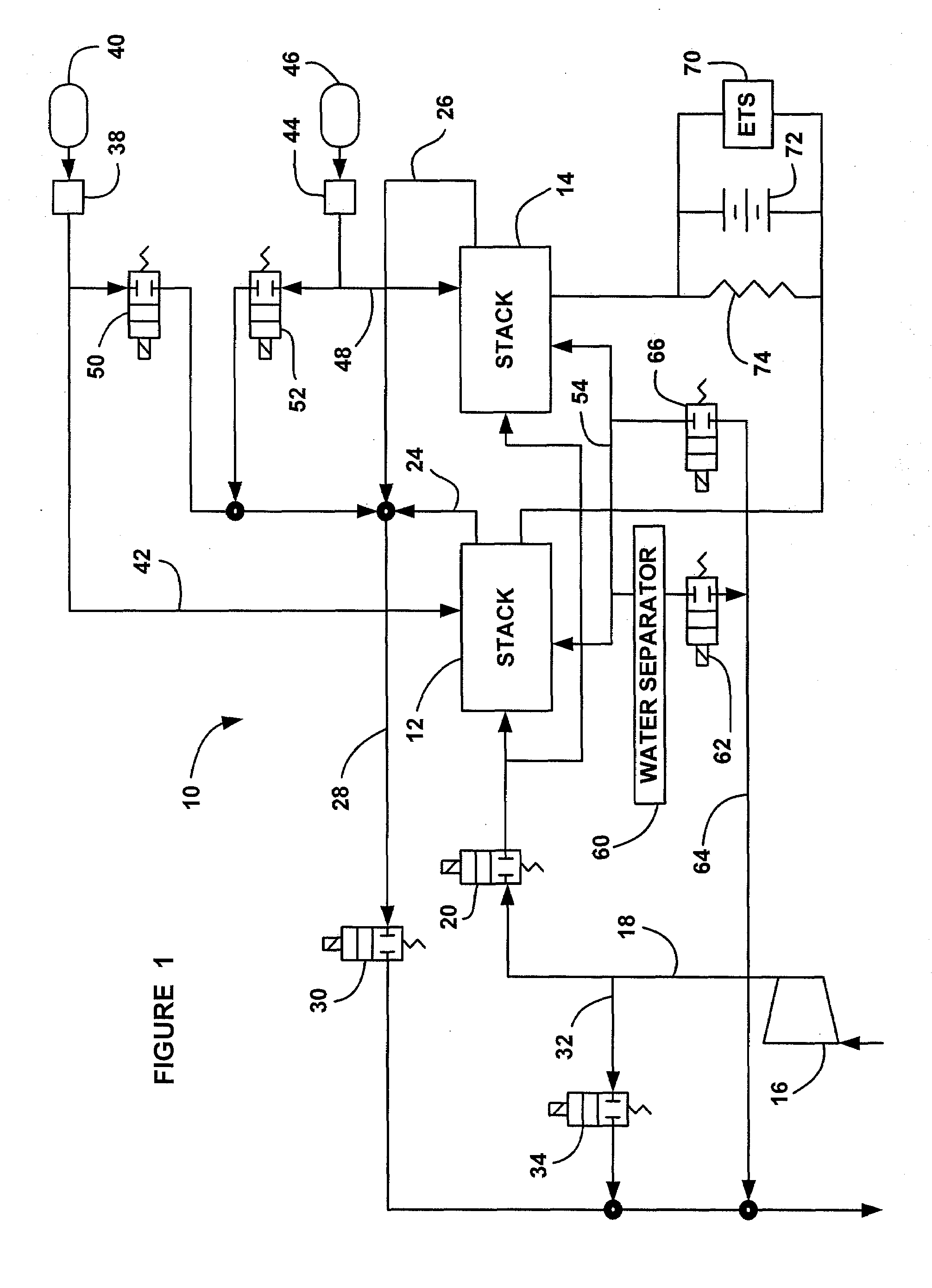
[0021]FIG. 1 is a schematic block diagram of a fuel cell system 10 including a first split fuel cell stack 12 and a second split fuel cell stack 14. A compressor 16 provides cathode input air on cathode input line 18 to the split stacks 12 and 14 through a normally closed cathode input valve 20. Cathode exhaust gas is output from the split stack on line 24 and cathode exhaust gas is output from the split stack 14 on line 26 where the cathode exhaust gas is combined into a single cathode output line 28. A normally closed cathode back pressure valve 30 controls the flow of the cathode exhaust gas through the line 28. A cathode by-pass line 32 between the input line 18 and the output line 28 allows the cathode...


PUM


Abstract

A system and method for reducing cathode carbon corrosion during start-up of a fuel cell stack. If a long enough period of time has gone by since the last system shutdown, then both the anode side and the cathode side of the stack will be filled with air. If the system includes split sub-stacks, then a start-up sequence uses a fast hydrogen purge through each sub-stack separately so as to minimize the time of the hydrogen/air front flowing through the anode side of the stacks. The start-up sequence then employs a slow hydrogen purge through the sub-stacks at the same time. If the time from the last shutdown is short enough where a significant amount of hydrogen still exists in the cathode side and the anode side of the sub-stacks, then the fast hydrogen purge can be eliminated, and the start-up sequence proceeds directly to the slow hydrogen purge.

Description

BACKGROUND OF THE INVENTION[0001]1. Field of the Invention[0002]This invention relates generally to a system and method for reducing catalyst degradation in the MEAs of a fuel cell stack at system start-up and, more particularly, to a system and method for reducing cathode catalyst degradation in the MEAs of a fuel cell stack at system shutdown and start-up that includes determining an anode purge velocity and time depending on how long the stack has been shutdown.[0003]2. Discussion of the Related Art[0004]Hydrogen is a very attractive fuel because it is clean and can be used to efficiently produce electricity in a fuel cell. A hydrogen fuel cell is an electro-chemical device that includes an anode and a cathode with an electrolyte therebetween. The anode receives hydrogen gas and the cathode receives oxygen or air. The hydrogen gas is dissociated in the anode to generate free protons and electrons. The protons pass through the electrolyte to the cathode. The protons react with the...

Claims


Application Information

Patent Timeline
IPC IPC(8): H01M8/02
CPCH01M8/04164H01M8/04223H01M8/04231H01M8/04753Y02E60/50H01M8/04955H01M8/249H01M2008/1095H01M8/0494H01M8/04302H01M8/04225
Inventor SALVADOR, JOHN P.LAKSHMANAN, BALSUALP, ABDULLAH B.ARTHUR, DAVID A.
Owner GM GLOBAL TECH OPERATIONS LLC
Why Eureka
Try Eureka