Intravenous deep vein thrombosis filter and method of filter placement

a filter and deep vein technology, applied in the field of vascular filters, can solve the problems of inefficient circulation, blood clots, and significant morbidity and mortality in the united states and throughout the world

Active Publication Date: 2008-07-31
BATISTE STANLEY
View PDF7 Cites 68 Cited by
  • Summary
  • Abstract
  • Description
  • Claims
  • Application Information

AI Technical Summary

Benefits of technology

[0012]To overcome the drawbacks of the prior art and provide additional benefits and features, a vascular filter and method of filter placement is disclosed. In one embodiment, the vascular filter includes a dispensing needle releasably attached to a syringe and a filter wi...

Problems solved by technology

Deep vein thrombosis (DVT) is a common problem and causes significant morbidity and mortality in the United States and throughout the world.
These blood clots typically occur due to slow or reduced blood flow through the deep veins such as when the patient cannot ambulate or otherwise efficiently circulate their blood.
Another cause of inefficient circulation may be due to structural damage to the veins such as general trauma or subsequent to surgical procedures.
Additionally, a blood clot may form in a deep vein due to a particular medical condition or a propensity for the patient to have a hypercoaguability state.
For example, a woman on birth control who smokes has an increased risk of forming blood clots and is thus predisposed to DVT.
For example, the clot may dislodge from a location in the deep vein of the patient's leg and migrate through the heart and come to rest in the patient's lung causing a pulmonary embolism (PE) resulting in restricted circulation and can cause sudden death for the patient.
However, this form of therapy has the disadvantage that due to the patient's inability to form blood clots (due to the medication), there is an increased risk of excessive bleeding should the patient become injured, sustain surgical complications, or develop internal hemorrhaging.
This form of treatment is risky and technically very difficult because the catheter has to be steered or navigated to a specific location in order to extract the clot.
Additionally, during a ...

Method used


Image

  • Intravenous deep vein thrombosis filter and method of filter placement
  • Intravenous deep vein thrombosis filter and method of filter placement
  • Intravenous deep vein thrombosis filter and method of filter placement

Examples


Embodiment Construction

[0035]In the following description, numerous specific details are set forth in order to provide a more thorough description of the present invention. It will be apparent, however, to one skilled in the art, that the present invention may be practiced without these specific details. In other instances, well-known features have not been described in detail so as not to obscure the invention.

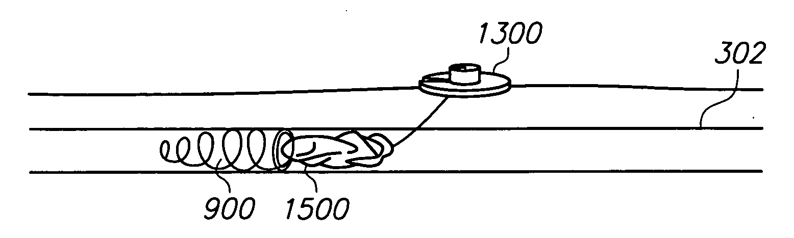
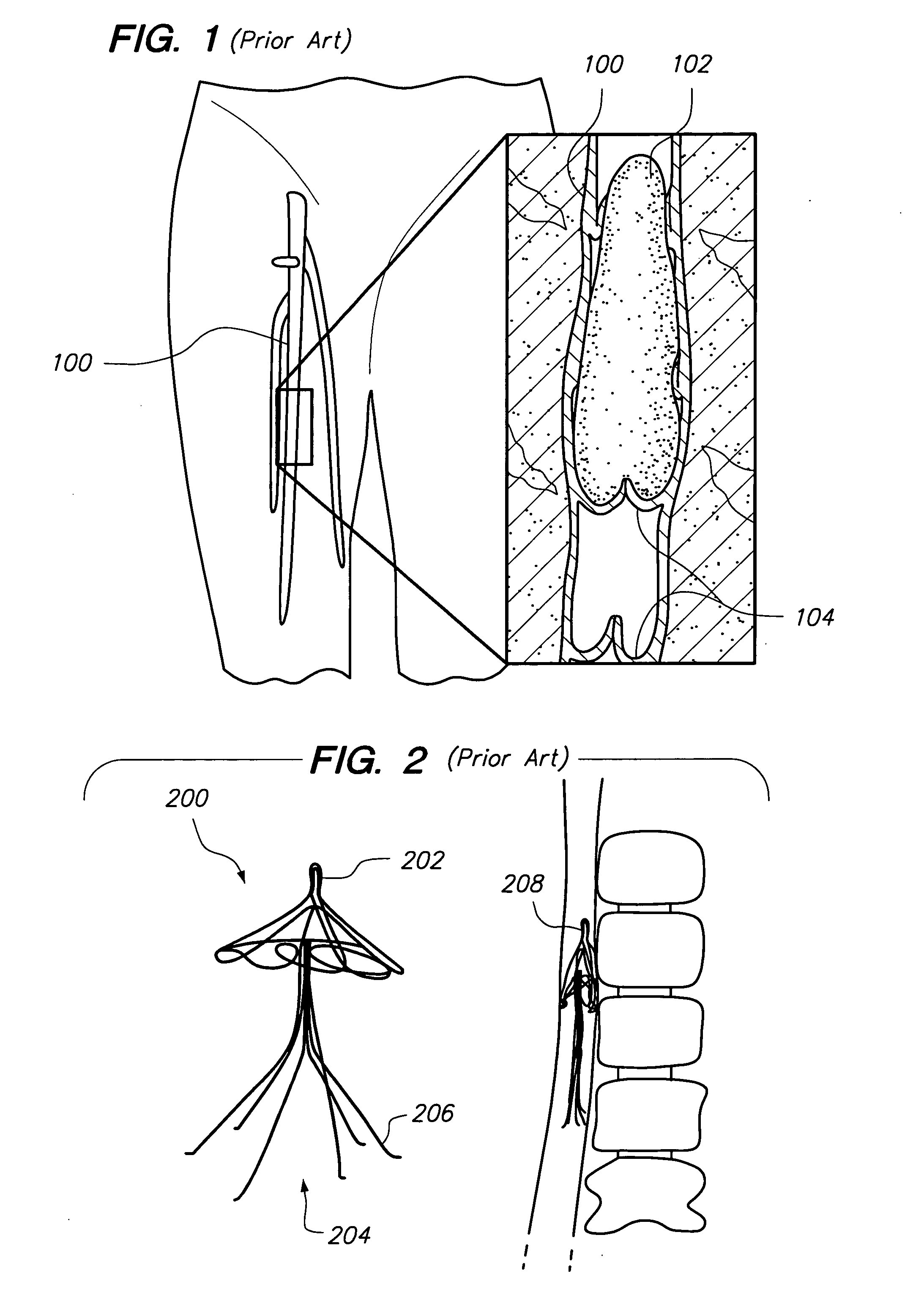
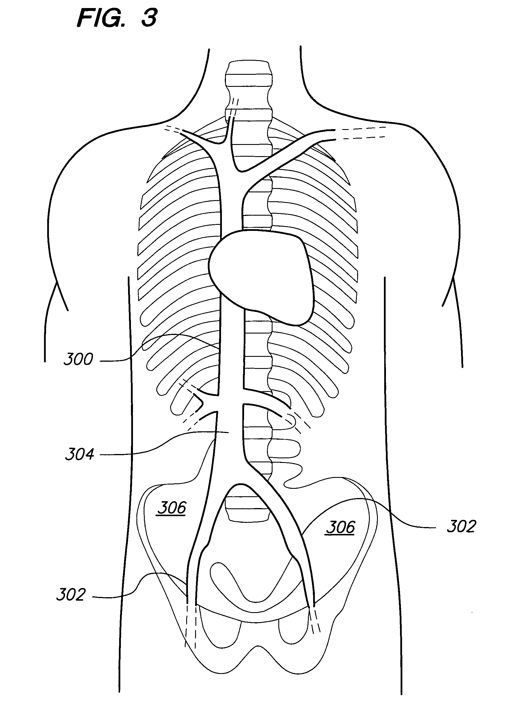
[0036]One of the primary concerns regarding deep vein thrombosis (DVT) is that should the thrombosis (blood clot) dislodge from the original location, the clot may travel to another region of the circulatory system and cause injury and or death to the subject. For example, if a DVT dislodges it may migrate through the heart and eventually re-lodge in the lung of the subject thus causing a pulmonary embolism (PE) which prevents adequate circulation and can cause sudden death. By placing an intravenous filter in the common femoral vein, the blood clot is captured and prevented from migrating to vulne...


PUM


Abstract

A vascular filter system and method are disclosed. In one embodiment, the filter system comprises a dispensing needle releasably attached to a filter dispenser which stores a length of filter wire. The filter wire dispenser has a guide tube which guides the filter wire into the needle and then into a vein during surgical implantation. The filter wire is configured to coil into a predetermined shape as it is deployed from the needle. The shape of the filter wire captures blood clots in the blood stream. Once the filter wire is deployed, the needle may be removed and a portion of the filter wire may be left protruding from the patient's skin surface to allow the filter wire to be secured by a fixation device. A syringe may be used to draw blood to confirm that the needle is properly positioned within a vein before the filter wire is deployed.

Description

1. CROSS-REFERENCE TO RELATED APPLICATIONS[0001]This application claims priority to U.S. Provisional Patent Application No. 60 / 898,939 filed on Jan. 31, 2007 titled IMPROVED INTRAVENOUS DEEP VEIN THROMBOSIS FILTER AND METHOD OF FILTER PLACEMENT.BACKGROUND OF THE INVENTION[0002]1. Field of the Invention[0003]The present invention relates to vascular filters and, in particular to surgically implanted vascular filters which capture blood clots to prevent the clots from migrating to other regions of the circulatory system.[0004]2. Related Art[0005]Deep vein thrombosis (DVT) is a common problem and causes significant morbidity and mortality in the United States and throughout the world. DVT is caused when a blood clot forms in the deep veins of the legs. These blood clots typically occur due to slow or reduced blood flow through the deep veins such as when the patient cannot ambulate or otherwise efficiently circulate their blood. Another cause of inefficient circulation may be due to st...

Claims


Application Information

Patent Timeline
IPC IPC(8): A61M29/00
CPCA61F2/01A61F2002/011A61F2230/0091A61F2002/016A61F2230/0006A61F2250/0059A61F2/011
Inventor BATISTE, STANLEY
Owner BATISTE STANLEY
Why Eureka
Try Eureka