System and method of chemical dilution and dispense

a chemical dilution and dispense technology, applied in the field of chemical supply systems, can solve the problems of requiring more space, corresponding material cost, and large footprint, and achieve the effect of precise and highly controllable manner

Inactive Publication Date: 2008-08-07
ENTEGRIS INC
View PDF5 Cites 6 Cited by
  • Summary
  • Abstract
  • Description
  • Claims
  • Application Information

AI Technical Summary

Benefits of technology

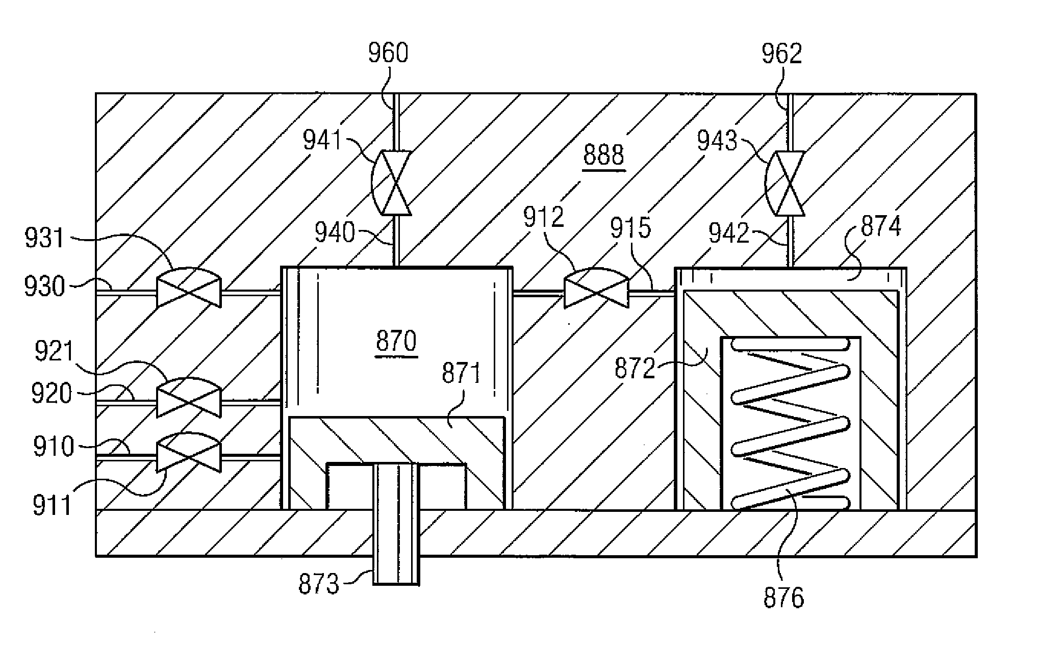
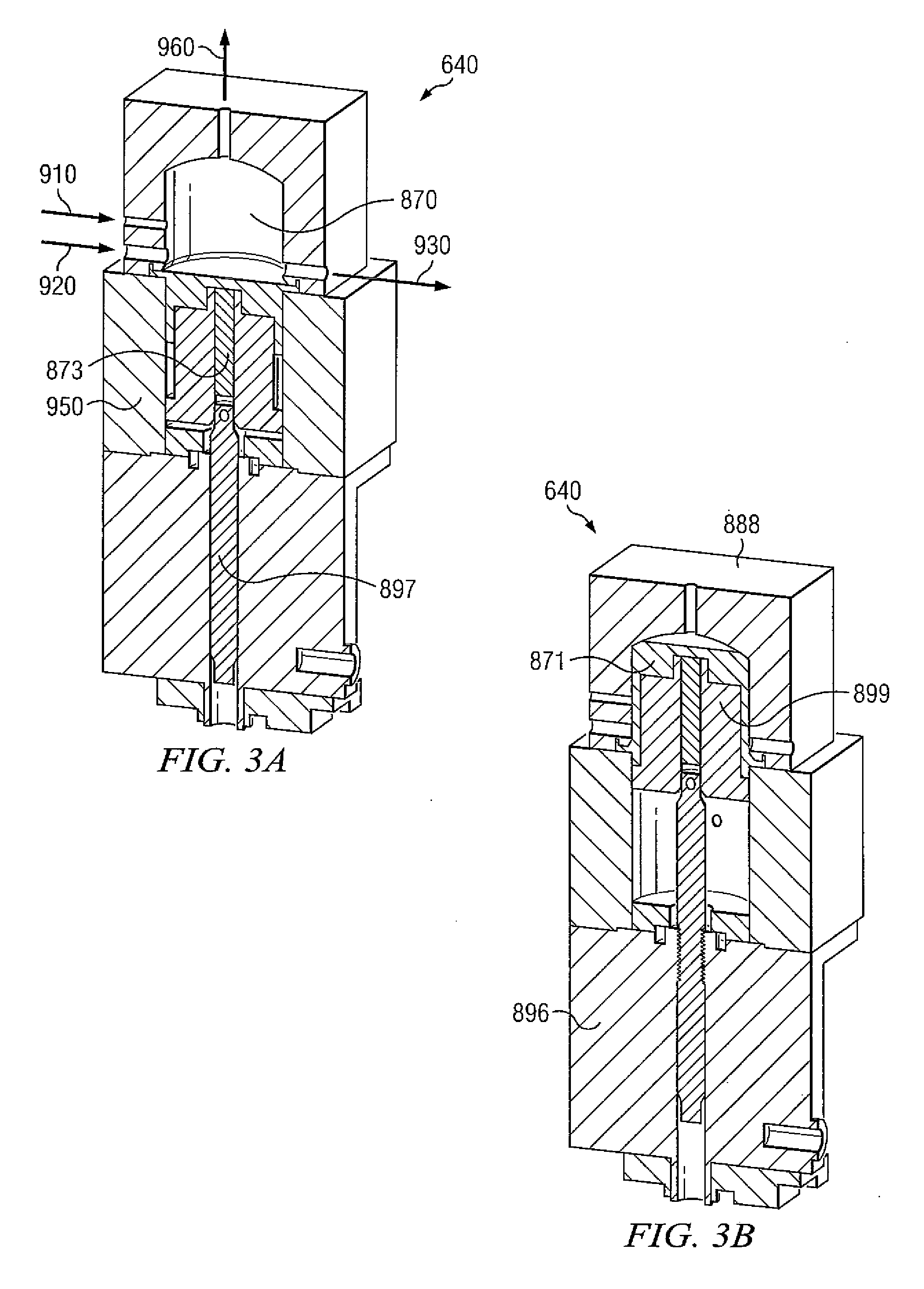
[0008]Embodiments of the disclosure include a pump or a multiple-pump system that can mix chemicals without dilution tanks and can dispense the mixture of chemicals in a precise and highly controllable manner, particularly useful in semiconductor manufacturing processes. In some embodiments, one or more piston pumps of similar displacement are used to mix and dispense the chemical directly. The uniformity of the mixture can be monitored with temperature sensor(s), pressure sensor(s), and any of the forms of concentration sensors that can be placed within the pump volume. A pump controller allows the possibility for closed loop control of the mixture key process parameters. Each controller channel also has the capabilities to measure other sensors such as temperature, dielectric constants and so on. These sensors could be used as a control or status signals to validate process integrity.
[0009]Embodiments described herein may have a lower volume of diluted chemicals (i.e., hold-up volume), which produces less chemical waste when the overall system is flushed. In some embodiments, smaller filters which can be placed inline with the pumps are utilized. As compared to larger filters which are utilized in prior art chemical supply systems and which are placed inline before and / or between mixing tanks, smaller filters may be easier to install, require less time to condition, and generally cost less than larger filters
[0010]Embodiments described herein may enable users to have higher control over reconfiguring their process chemistry mix ratios. The level sensors utilized in prior art chemical supply systems generally only produce discrete mix ratios. Thus, in prior art chemical supply systems, reconfiguring of the mix ratios requires moving the position of the level sensors. In embodiments disclosed herein, a user can change the parameters downloaded electronically to the pump controller to change the mixture proportions, making reconfiguring of the mix ratios much easier and faster.
[0011]Embodiments disclosed herein provide a variety of advantages. One advantage is the lower space requirement and hence smaller footprint due to the fact that dilution tanks are not required. The elimination of dilution tanks also provides the advantage of lower cost as corresponding instrumentation (e.g., multiple level sensors) and plumbing for such dilution tanks are also eliminated. Moreover, because fewer components such as level sensors are used, embodiments described herein may have a lower maintenance cost due to shorter assembly times and improved reliability.

Problems solved by technology

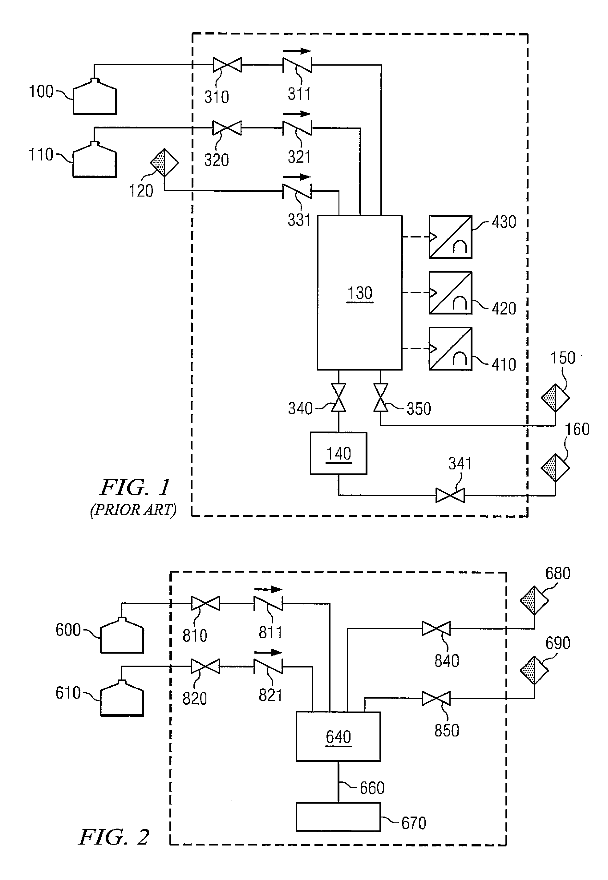
One problem common to prior art chemical supply systems such as one shown in FIG. 1 is that sensors 410, 420 and 430 must be physically placed at particularly selected positions on tank 130.
Prior art chemical supply systems thus contains dilution tanks, volume level or gravimetric instrumentation, and associated recirculation pumps and plumbing, requiring more space with a larger footprint and corresponding material cost.

Method used


Image

  • System and method of chemical dilution and dispense
  • System and method of chemical dilution and dispense
  • System and method of chemical dilution and dispense

Examples


Embodiment Construction

[0020]The invention and the various features and advantageous details thereof are explained more fully with reference to the non-limiting embodiments that are illustrated in the accompanying drawings and detailed in the following description. Descriptions of well known starting materials, processing techniques, components and equipment are omitted so as not to unnecessarily obscure the disclosure in detail. Skilled artisans should understand, however, that the detailed description and the specific examples, while disclosing preferred embodiments, are given by way of illustration only and not by way of limitation. Various substitutions, modifications, additions or rearrangements within the scope of the underlying inventive concept(s) will become apparent to those skilled in the art after reading this disclosure.

[0021]Reference is now made in detail to the exemplary embodiments, examples of which are illustrated in the accompanying drawings. Wherever possible, the same reference numbe...


PUM

PropertyMeasurementUnit
speedaaaaaaaaaa
concentrationaaaaaaaaaa
chemical concentrationsaaaaaaaaaa

Abstract

Embodiments disclosed herein provide a pump or a multiple-pump system that can mix chemicals without dilution tanks and can dispense the mixture of chemicals in a precise and highly controllable manner, particularly useful in semiconductor manufacturing processes. In some embodiments, one or more piston pumps of similar displacement are used to mix and dispense the chemical directly. A first valve is opened to a first chemical source. A piston is moved in a first direction to a selected position in a chamber to draw the first chemical into the chamber. The first valve is closed and a second valve is opened to a second chemical source. The piston is moved in the first direction to a second position in the chamber to draw in the second chemical and mix the chemicals. The second valve is closed and the piston is moved to dispense the fluids through a dispense port.

Description

CROSS-REFERENCE TO RELATED APPLICATIONS[0001]This application claims priority from Provisional Patent Applications No. 60 / 899,299, filed Feb. 2, 2007, entitled “CHEMICAL DILUTION AND DISPENSE PUMP” and No. 60 / 925,220, filed Apr. 19, 2007, entitled “CHEMICAL DILUTION AND DISPENSE PUMP,” the entire contents of which are expressly incorporated herein by reference for all purposes.TECHNICAL FIELD[0002]This disclosure relates generally to chemical supply systems used in the semiconductor manufacturing industry and more particularly to a system and method for mixing and dispensing chemicals in a precise and highly controllable manner without using dilution tanks.BACKGROUND OF THE RELATED ART[0003]Prior art chemical supply systems used in the semiconductor manufacturing industry include tanks to mix or dilute chemicals. As FIG. 1 exemplifies, in a prior art chemical supply system, chemicals are mixed in tank 130 by filling tank 130 with a quantity of a chemical from first source or contain...

Claims


Application Information

Patent Timeline
Patent Type & Authority Applications(United States)
IPC IPC(8): B67D5/56G05D11/13B01F15/04B67D7/74
CPCB01F3/088G05D11/132B01F5/0685Y10T137/0329B01F23/49B01F25/4512
Inventor CLARKE, MICHAELLAVERDIERE, MARCMCLOUGHLIN, ROBERT F.NIERMEYER, J. KARLSMITH, JOSEPH E.MOLLICA, ROSARIO
Owner ENTEGRIS INC
Why Eureka
Try Eureka