
Exposure control for phase shifting photolithographic masks

a photolithographic mask and phase shifting technology, applied in the field of phase shifting photolithographic masks, can solve the problems of mask manufacturing cost increase and mask cost increase, and achieve the effects of improving throughput, improving critical dimension uniformity, and improving the effect of quality

Inactive Publication Date: 2008-08-07
SYNOPSYS INC
View PDF54 Cites 3 Cited by
  • Summary
  • Abstract
  • Description
  • Claims
  • Application Information

AI Technical Summary

Benefits of technology

[0016]In various embodiments, the relative dosing between the exposure of the phase shifting pattern and the trim pattern is expressed by a ratio 1.0:r, where r>0.0. In some embodiments, 2.0<r<4.0, so that the exposure dosing of the binary pattern is from 2 to 4 times greater than the dosing of the phase shifting pattern. One embodiment uses a 1:2 ratio, another a 1:3 ratio. The greater exposure of the trim pattern facilitates clearing of cuts, or openings, while preventing exposure of the features defined by the phase shifting pattern. In some embodiments, r is determined from simulation results for a particular optical lithography model, e.g. stepper, wavelength, resist measurements, etc.
[0017]Additionally, both patterns are provided on a single reticle in one embodiment of the present invention. A single reticle with multiple patterns can increase mask manufacturing costs. However, the cost of the mask is justified because the use of the single reticle can improve yield, and save manufacturing steps and time. A multiple pattern reticle can allow more rapid exposure of the layer of material using both the phase shifting pattern and the trim pattern. The layout of patterns on the single reticle can be simple (one of each) or more complex (multiple phase patterns; multiple binary patterns; one-dimensional; two-dimensional; etc.) The dosing ratio r for a layer to be exposed can be implemented, for example using constant exposure doses to each pattern with the ratio of the number of phase shifting patterns and to the number of trim patterns on the mask set equal to the dosage ratio 1.0:r. In this example, the exposure dosage is another parameter that is not changed between exposures of the phase shift and trim patterns.
[0021]Resulting ICs produced according to embodiments of the invention can include a large number of subwavelength features due to the use of phase shifting and those features will tend to be extremely well defined because of the high quality energy profile achieved, and the ability to rapidly develop the photoresist by using embodiments of the invention (shorter and more uniform time intervals between exposures; fewer mistakes in lithography settings, fewer mistakes in optical settings; etc.)

Problems solved by technology

A single reticle with multiple patterns can increase mask manufacturing costs.
However, the cost of the mask is justified because the use of the single reticle can improve yield, and save manufacturing steps and time.

Method used


Image

  • Exposure control for phase shifting photolithographic masks
  • Exposure control for phase shifting photolithographic masks
  • Exposure control for phase shifting photolithographic masks

Examples


Embodiment Construction

Overview

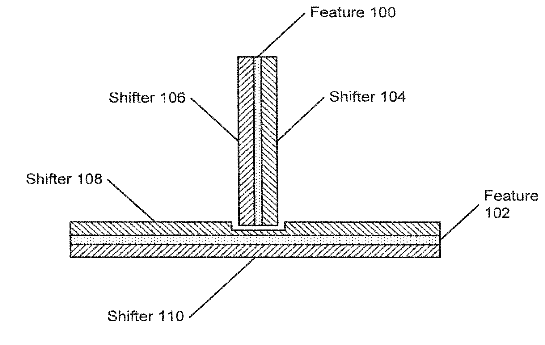
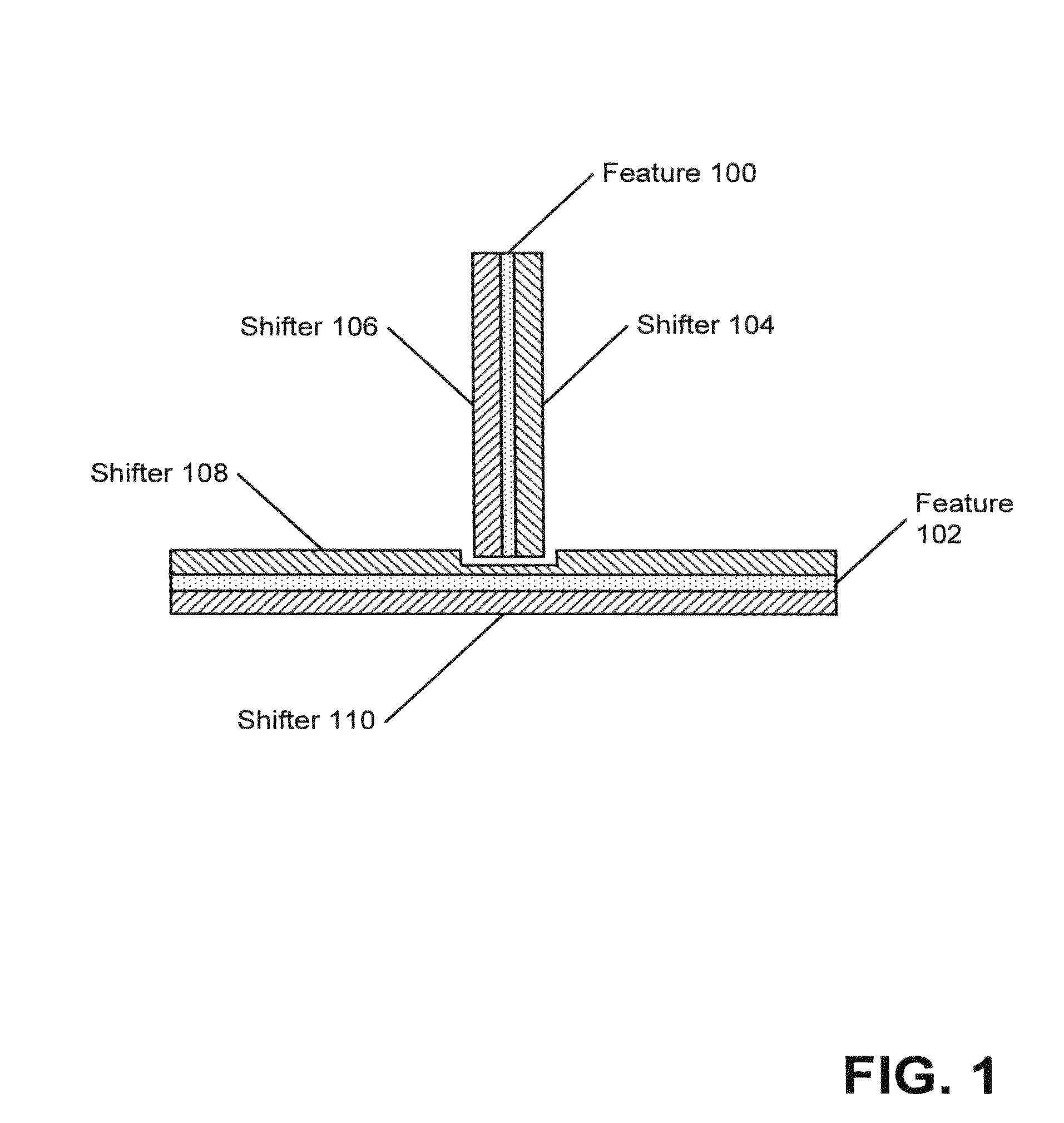
[0035]First, exposure settings for use in conjunction with phase shifting masks that produce substantial portions of a pattern of a layer on an integrated circuit (IC) using phase shifting will be considered. Next, relative dosing considerations between the phase shifting pattern exposure and the binary, trim pattern exposure will be considered. Finally, approaches for using a single reticle in the production of ICs using phase shifting will be considered. (As used herein, the terms “mask” and “reticle” are synonyms, generally referring to a device carrying patterns, also called layouts, for photolithographic exposure used in manufacture of semiconductor wafers or other workpieces.)

Exposure Settings

[0036]In one embodiment of the invention, an optical lithography exposure system, generally referred to as a stepper, has a setting of members of a set of one or more optical parameters that control characteristics of exposures, the settings used to expose the phase shifting patte...


PUM

PropertyMeasurementUnit
wavelengthaaaaaaaaaa
phaseaaaaaaaaaa
phase shiftingaaaaaaaaaa

Abstract

Mask and integrated circuit fabrication approaches are described to facilitate use of so called “full phase” masks. This facilitates use of masks where substantially all of a layout is defined using phase shifting. More specifically, exposure settings including relative dosing between the phase shift mask and the trim masks are described. Additionally, single reticle approaches for accommodating both masks are considered. In one embodiment, the phase shifting mask and the trim mask are exposed using the same exposure conditions, except for relative dosing. In another embodiment, the relative dosing between the phase and trim patterns is 1.0:r, 2.0<r<4.0. These approaches facilitate better exposure profiles for the resulting ICs and can thus improve chip yield and increase throughput by reducing the need to alter settings and / or switch reticles between exposures.

Description

RELATED APPLICATIONS[0001]This application is a continuation of U.S. patent application Ser. No. 10 / 841,276 filed on 7 May 2004, which is a continuation of U.S. patent application Ser. No. 09 / 972,428 filed on 5 Oct. 2001, which is related to, claims the benefit of priority of, and incorporates by reference, the U.S. Provisional Patent Application Ser. No. 60 / 296,788 filed 8 Jun. 2001 entitled “Phase Conflict Resolution for Photolithographic Masks” having inventors Christophe Pierrat and Michel Côté and assigned to the assignee of the present invention, and which application is related to, claims the benefit of priority of, and incorporates by reference, the U.S. Provisional Patent Application Ser. No. 60 / 304,142 filed 10 Jul. 2001 entitled “Phase Conflict Resolution for Photolithographic Masks” having inventors Christophe Pierrat and Michel Côté and assigned to the assignee of the present invention.BACKGROUND OF THE INVENTION[0002]1. Field of the Invention[0003]The present invention...

Claims


Application Information

Patent Timeline
Patent Type & Authority Applications(United States)
IPC IPC(8): G03F7/22G03F1/00G03F7/20H01L21/027
CPCG03F1/144G03F7/70425G03F7/70558G03F7/70466G03F7/70433G03F1/26G03F1/70
Inventor PIERRAT, CHRISTOPHECOTE, MICHEL LUC
Owner SYNOPSYS INC
Learn More