
Cryogenic Immersion Microscope

Inactive Publication Date: 2008-08-14
RGT UNIV OF CALIFORNIA
View PDF4 Cites 6 Cited by
  • Summary
  • Abstract
  • Description
  • Claims
  • Application Information

AI Technical Summary

Benefits of technology

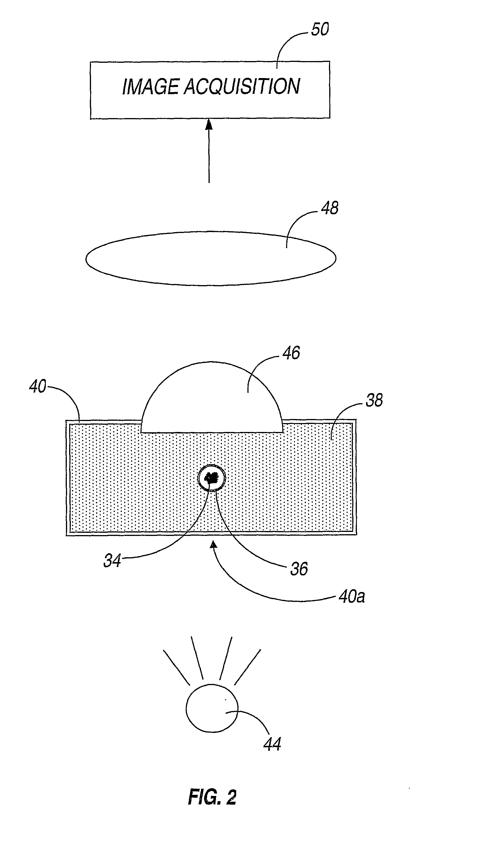
[0013]A cryogenic immersion liquid 38 between the sample holder 36 and the objective lens 46 allows for the sample holder 36 to be cylindrical without loss of resolution. The liquid 38 significantly reduces image artifacts which would otherwise be present due to the curved interfaces and refractive index differences between the specimen 34 and the objective lens 46 in air.
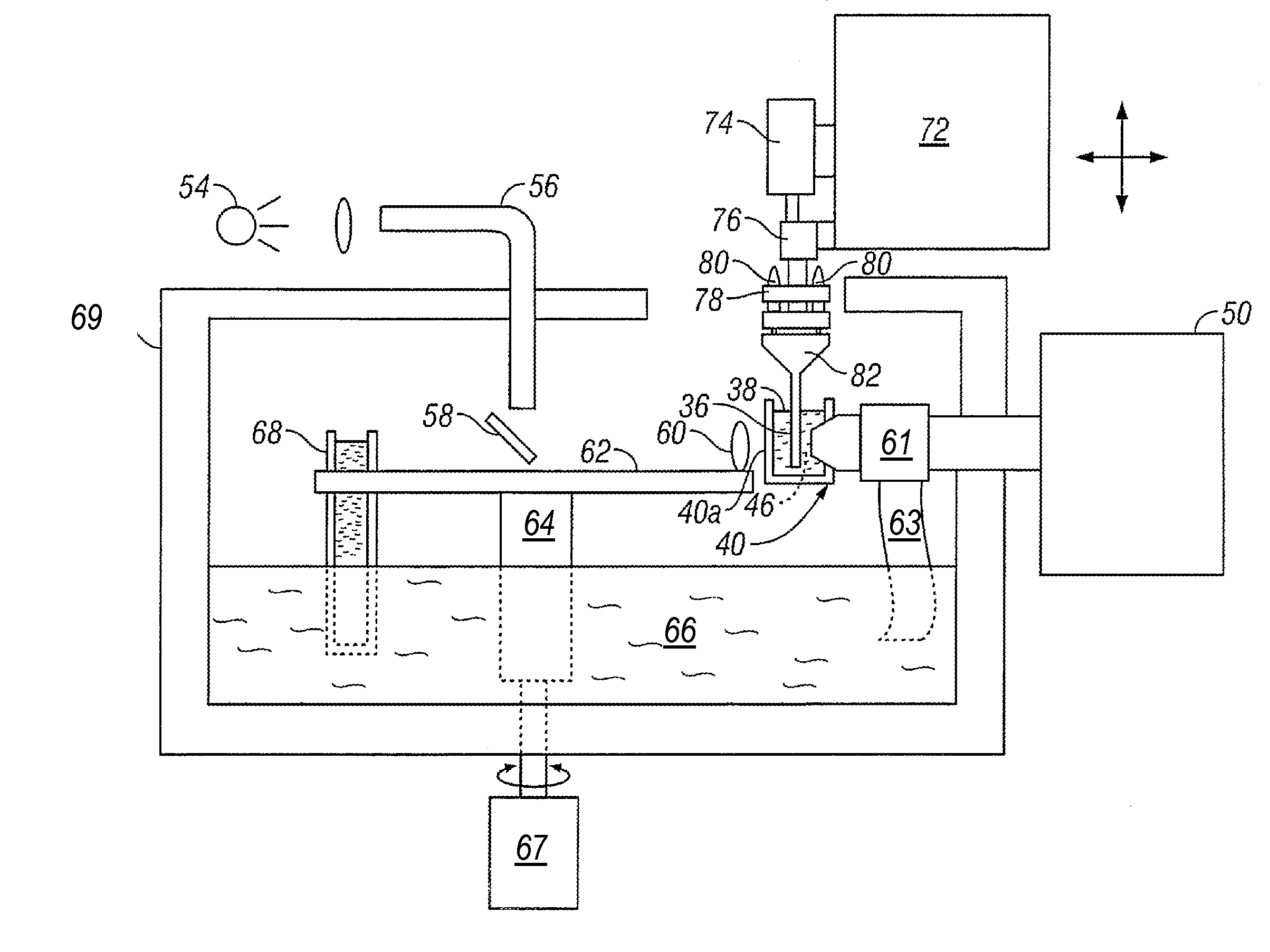
[0017]In one embodiment, the sample carrier is a capillary as illustrated in FIG. 5. The capillary can be made by softening glass tubing and stretching the softened glass to form a thin capillary using conventional glass working techniques. The capillary can then be cut to a desired size. FIG. 5 depicts a capillary 86 positioned at the end of a glass tube 85. The glass tube 85 has an upper or initial diameter 88. Capillary 86 has diameter 90 and length 92. In one embodiment, upper diameter 88 is approximately 1 millimeter. In one embodiment, capillary diameter 90 is approximately 10 microns. In one embodiment, length 92 is approximately 300 microns. In one embodiment, the diameter 90 is approximately equal to the diameter of cells that are to be imaged. Thus, a linear array of cells can fill capillary 86 for imaging. In one embodiment, samples are loaded into the capillary 86 by introducing them into the glass tube 85 and then forcing the samples into capillary 86 such as by centrifugation or increased pressure. In another embodiment, samples are loaded into the capillary 86 by applying a negative pressure to the glass tube 85 and pulling the samples into the tube through the capillary tip 91. In one embodiment, the capillary 86 comprises quartz glass. In another embodiment, the capillary 86 is Pyrex™ glass.
[0021]In one embodiment, the cryogenic optical microscope described above is combined with an x-ray microscope by using a common x,y,z stage 72 which is configured to position a sample alternately in the cryogenic liquid reservoir 38 in an optical illumination path, and then neat to a micro zone plate in the beamline or x-ray illumination path of the x-ray (tomography) microscope 86. When using the x-ray microscope, the sample can be kept cold by being placed in a stream of He or N2 gas cooled with liquid nitrogen, as described in the PCT patent application above. Combining optical microscopy with x-ray tomography has the advantage that image features observed with the optical microscope can be correlated with image features produced with x-ray tomography. Thus a much richer picture of the biological structures observed in cells can be obtained. The high spatial resolution and low sample temperature used in the cryogenic light microscope allow for a much enhanced photostability of conventional fluorescent probes (on the order of 100×). This enables cell fluorescent measurements such as Fluorescent Resonance Energy Transfer (FRET) at much lower fluorescent probe concentrations, which measurements can be superposed on high spatial resolution x-ray images of unlabled cell components.

Problems solved by technology

Although the need for obtaining magnified images of frozen specimens exists in many applications, the advantages of liquid immersion have never been achieved, due either to freezing of the index matching liquid or melting of the frozen specimen

Method used


Image

  • Cryogenic Immersion Microscope
  • Cryogenic Immersion Microscope
  • Cryogenic Immersion Microscope

Examples


Embodiment Construction

[0009]The following detailed description is directed to certain specific embodiments of the invention. However, the invention can be embodied in a multitude of different ways. In this description, reference is made to the drawings wherein like parts are designated with like numerals throughout.

[0010]Referring now to FIG. 2, one embodiment of a cryogenic immersion microscope is illustrated. In this system, a specimen 34 is fixed inside a cylindrical sample holder 36. The sample holder 36 is immersed in a reservoir of a cryogenic liquid 38. The cryogenic liquid 38 is inside a container 40, which advantageously includes at least one transparent wall or wall portion 40a that allows light from a condenser / light source 44 to pass through the specimen 34 and into an objective lens 46. The objective lens 46 extends through an opening in the container 40, and is at least partially immersed in the cryogenic liquid 38, that is to say that at least one surface, the surface facing the sample hol...


PUM


Abstract

A cryogenic immersion microscope whose objective lens is at least partially in contact with a liquid reservoir of a cryogenic liquid, in which reservoir a sample of interest is immersed is disclosed. When the cryogenic liquid has an index of refraction that reduces refraction at interfaces between the lens and the sample, overall resolution and image quality are improved. A combination of an immersion microscope and x-ray microscope, suitable for imaging at cryogenic temperatures is also disclosed.

Description

CROSS-REFERENCE TO RELATED APPLICATIONS[0001]This application claims priority to U.S. Patent Provisional Application 60 / 673,274, filed Apr. 2, 2005, which is incorporated by reference herein. This application is also related to Patent Application PCT / US05 / ______, Attorney docket no IB-1981 PCT, filed Apr. 20, 2006.STATEMENT OF GOVERNMENT INTEREST[0002]The invention described and claimed herein was made in part utilizing funds supplied by the U.S. Department of Energy under Contract Number DE-AC03-76SF00098 and by the National Institutes of Health under Grant Number R01 GM63948-03. The U.S. government has certain rights in this invention.TECHNICAL FIELD[0003]The present invention relates generally to the field of microscopy, and, more specifically, to immersion microscopy at cryogenic temperatures.BACKGROUND ART[0004]Oil and water immersion microscopes have been utilized for many years, and a wide variety of microscope designs using immersion liquids are commercially available. The f...

Claims


Application Information

Patent Timeline
IPC IPC(8): G02B21/02
CPCG02B21/33G02B21/28
Inventor LE GROS, MARKLARABELL, CAROLYN A.
Owner RGT UNIV OF CALIFORNIA
Learn More