Device for feeding electrical energy from an anergy source

a technology of electrical energy and anergy source, which is applied in the direction of electric variable regulation, process and machine control, instruments, etc., can solve the problems of increasing losses, increasing losses, and increasing losses of semi-conductor components, so as to reduce ripple current loads, the energy source of solar generators is particularly favorable, and the internal impedance is high

Inactive Publication Date: 2008-08-14
SMA SOLAR TECH AG
View PDF6 Cites 97 Cited by
  • Summary
  • Abstract
  • Description
  • Claims
  • Application Information

AI Technical Summary

Benefits of technology

[0042]According to another preferred embodiment of the apparatus of the invention, it is intended to reduce the ripple current loads in the energy source and in the intermediate circuit capacitor. This is achieved in that several resonant inverters are connected in parallel at the energy source on the primary side and are connected to a common intermediate circuit capacitor on the secondary side, the various resonant converters being clocked at different times.
[0043]A system having a device the energy source of which is a solar generator is particularly favourable. Said generator has quite high internal impedance but also quite high no-load voltage by virtue of the typical characteristic line of the solar cell. The invention may however also be utilized to advantage if the energy source is a fuel cell, a battery, a wind power plant wit

Problems solved by technology

Due to the switching losses in the semi-conductor switches of the low-frequency inverter, the losses increase with rising voltage at the energy source.
The low-frequency transformer is of quite large dimensions and is very heavy.
Furthermore, the semi-conductor losses increase with rising voltage at the energy source.
Although resonance converters are highly efficient, they cannot be utilized for adapting the voltage.
Such an adapter stage however causes additional costs and requires additional space.
Furthermore, additional losses are originated in such a stage.
Accordingly, this not only makes it necessary to provide for an additional adapter stage, which involves more components, more costs and more space, but also suffers from the serious disadvantage that the efficiency is reduced by such an additional stage.
If a high-frequency inverter is configured

Method used


Image

  • Device for feeding electrical energy from an anergy source
  • Device for feeding electrical energy from an anergy source
  • Device for feeding electrical energy from an anergy source

Examples


Embodiment Construction

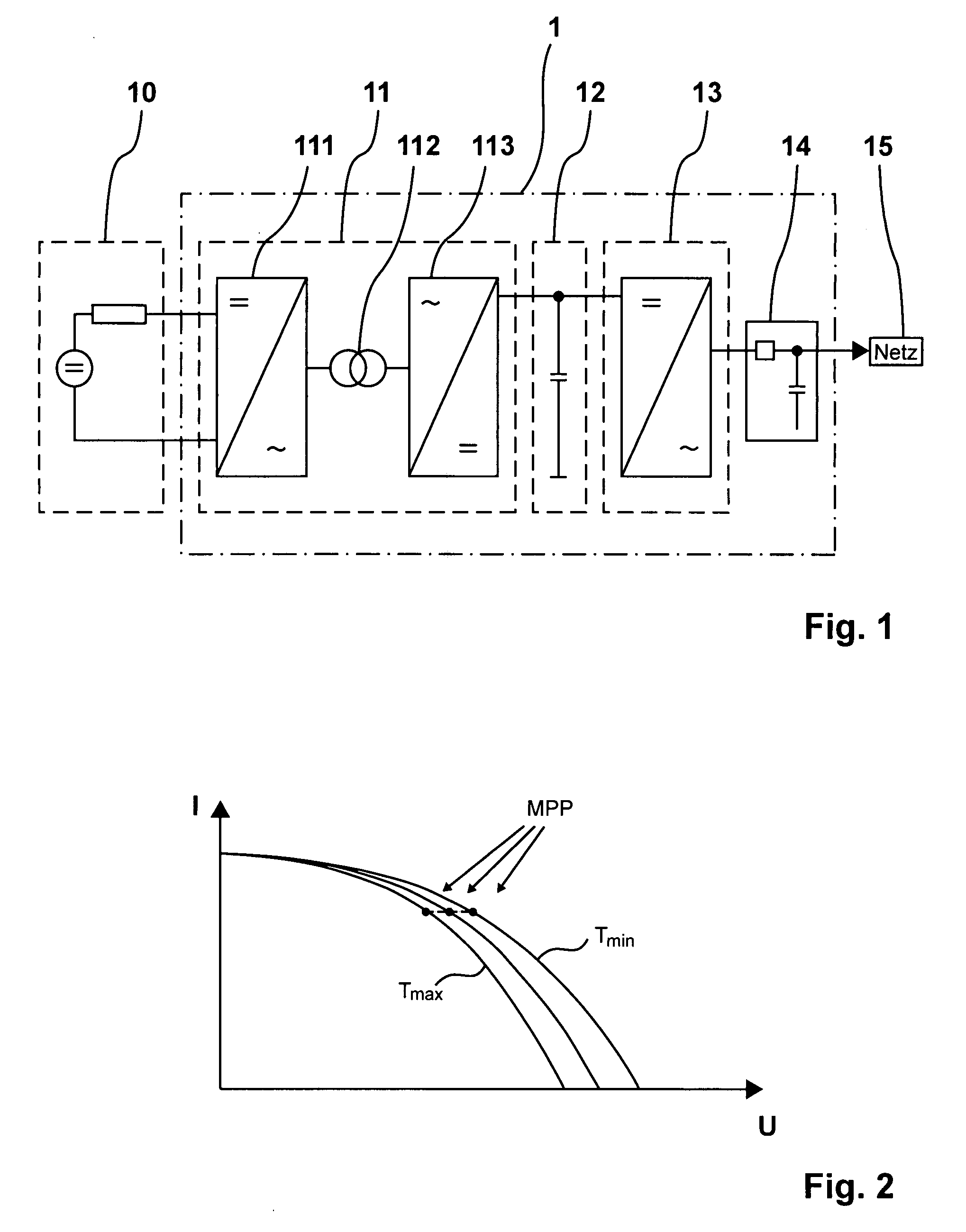
[0055]The fundamental function of the device 1 of the invention will be first explained referring to FIG. 1, reference being made to the FIGS. 5 through 7 as well.

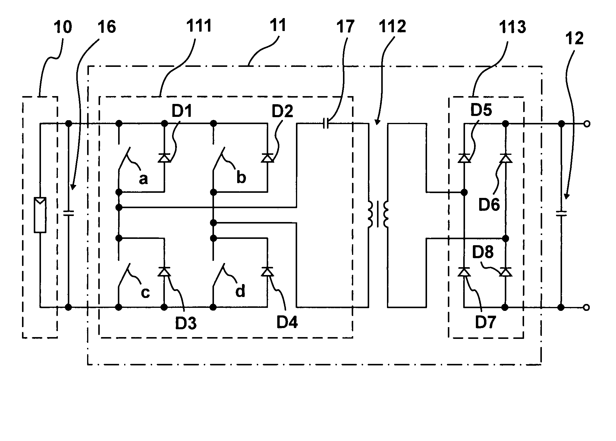
[0056]The device 1 comprises a resonant converter or rather a resonant inverter 11 (DC / DC inverter) with a high-frequency inverter 111 and a high-frequency rectifier 113, both being connected together by a high-frequency transformer 112 connected therein between in order to provide for galvanic isolation. The converter or inverter 11 virtually is (without regen-capable inverter) a DC / DC converter and serves for voltage adaptation and galvanic isolation. The transformer 112 is disposed in the resonant inverter 11. A direct voltage output of the high-frequency rectifier 113 leads to a direct voltage intermediate circuit (intermediate circuit capacitor 12), as can be seen from FIG. 1. As the last stage, the device 1 has a regen-capable inverter 13 connected downstream of the direct voltage intermediate circuit (intermediate c...


PUM


Abstract

A device (1) for feeding electrical energy from an energy source with variable source voltage into an electric power supply network (15), said device (1) including a transformer (112) for galvanic isolation, a resonant inverter (11) with semi-conductor switches (a-d; A, B), one or several resonant capacitors (17; 18, 19; 20, 21) and one rectifier (113), is: intended to provide high efficiency and have galvanic isolation. This is achieved in that the resonant inverter (11) is operated in the full resonant mode if the operating voltage is in an operation point (MPP) and in the hard-switching mode if the voltages exceed the operation point (MPP).

Description

CROSS TO RELATED APPLICATIONS[0001]This application claims Priority from European Application No. EP 07002682.8 filed on Feb. 8, 2007.FIELD OF THE INVENTION[0002]A device for feeding electrical energy from an energy source with variable source voltage into an electric power supply network, said device including a transformer for galvanic isolation, a resonant inverter with semi-conductor switches, one or several resonant capacitors and one rectifier. Many electrical energy sources, more specifically solar generators, wind power plants with what are termed PM generators, speed-variable combustion motors, fuel cells, batteries and the like, often have a highly variable voltage and quite high an inner impedance. Usually, such energy sources are direct voltage sources but energy sources having a one-phase or a three-phase alternating voltage with variable frequency may also have a highly variable source voltage.[0003]An adapter device is needed to feed electrical energy from such source...

Claims


Application Information

Patent Timeline
IPC IPC(8): H02M3/335
CPCH02J3/387H02J2001/004H02M3/337H02M3/3372H02M2001/007Y02B70/1433H02J3/382H02J3/386H02M2001/0058Y02E10/563Y02E10/763Y02B70/1491H02J3/383H02J2300/30H02J2300/10H02J2300/28H02J2300/20H02J2300/24H02J3/381Y02B70/10Y02E10/56Y02E10/76H02M1/0058H02M1/007H02M3/33573H02M3/33571H02M3/01
Inventor FALK, ANDREAS
Owner SMA SOLAR TECH AG
Why Eureka
Try Eureka