[0005]Because a component (of the eccentric) that is mounted on the fitting part is coated on its inner side and / or its outer side, or the associated fitting part, in the region interacting with the component, is coated with a
thin layer which has a lower
coefficient of friction than the material of the (metallic) component, the friction on two interacting surfaces can be reduced in a specific manner, thus improving the efficiency of the fitting. By way of the (sliding) layer which is formed on a side of the component, which side bears, in a known embodiment, against a pressed-in sliding bearing or rolling bearing, such a low degree of friction is achieved that the pressed-in sliding bearing or rolling bearing may be omitted, i.e. a component is saved and construction space obtained, for example in order to increase the strength. The coated eccentric component or the eccentric component interacting with the
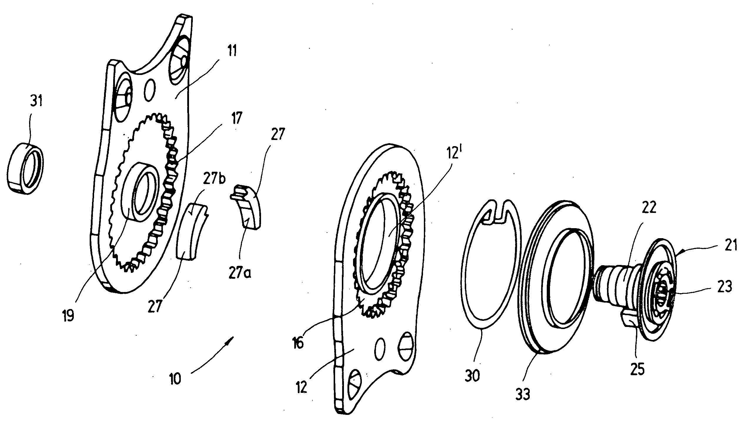
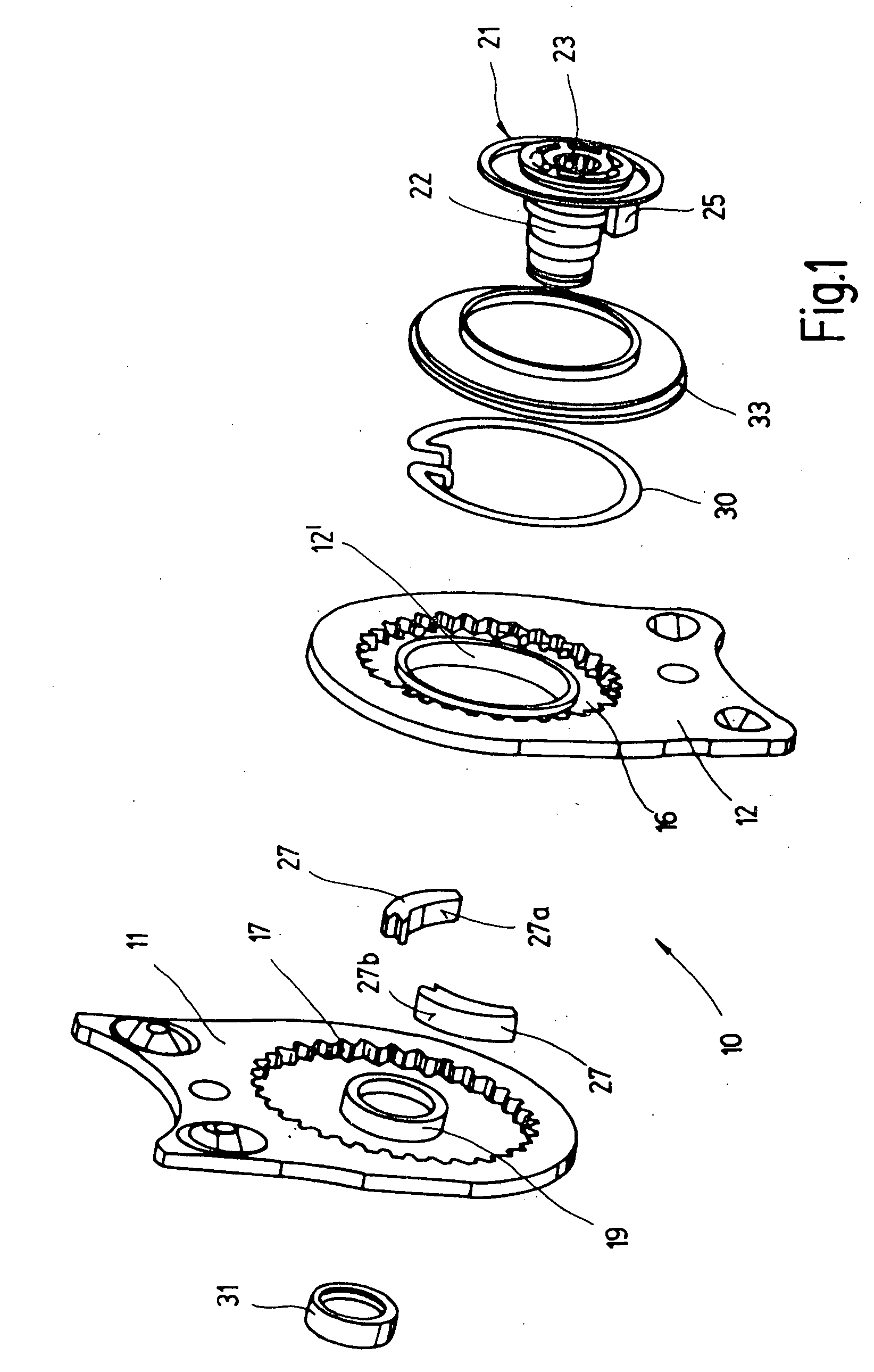
coated surface may also be a (preferably metallic) driving ring of a multi-part driver, which driving ring is arranged radially between the wedge segments and the associated fitting part. The wedge segments within the context of the invention do not have to be geometrically genuine segments but rather may also be formed in each case on a disk, with the two (eccentric) disks then being arranged offset axially with respect to each other.
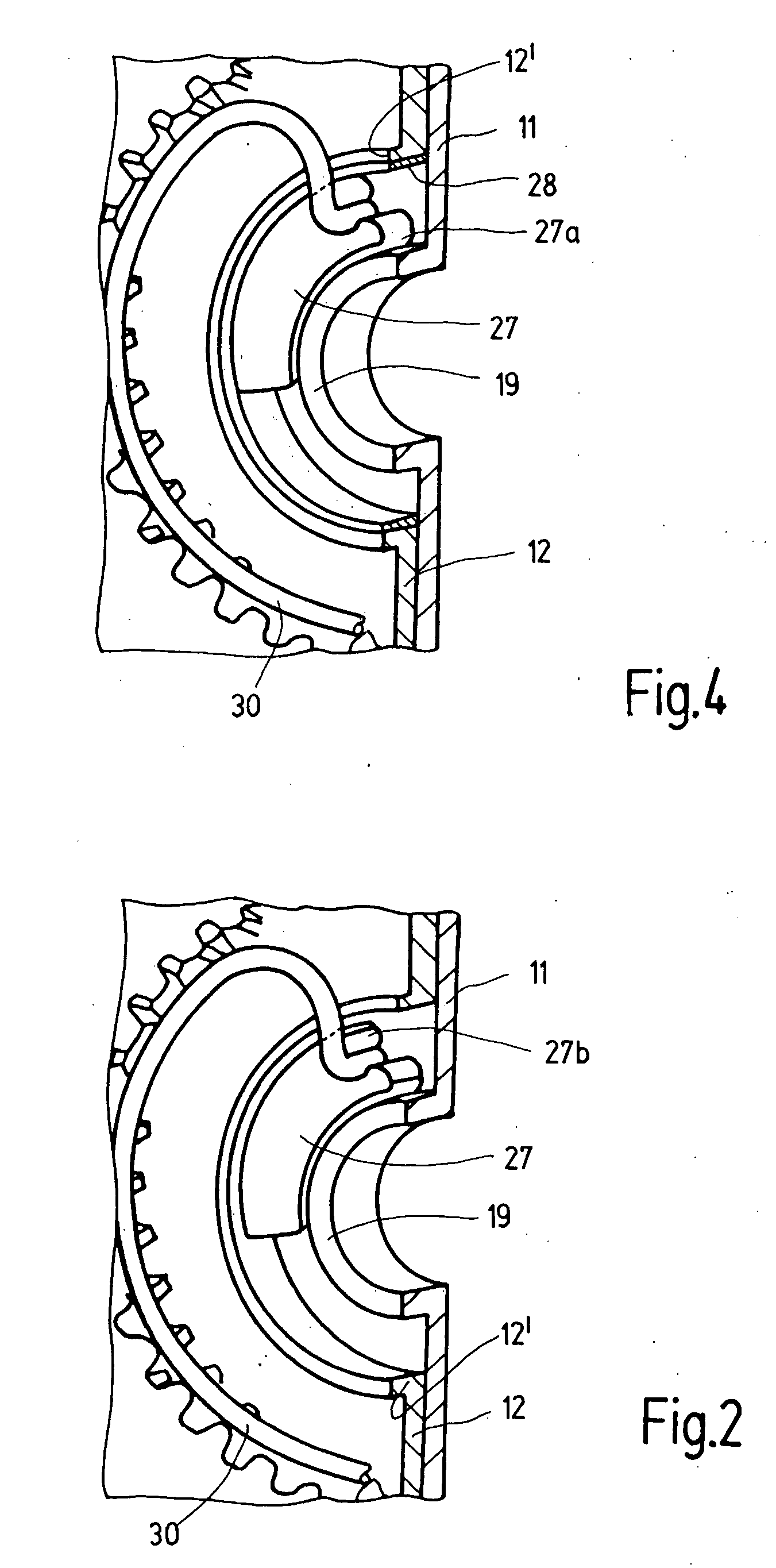
[0006]If the layer is used at a location which otherwise has a high degree of friction, for example on the wedge-segment inner side which faces a collar formation, the lower range fluctuation of the
coefficient of friction enables the design to be closer to the self-locking limit without impairing the reliability of movement of the self-locking fitting. If the fitting is prevented from running because of other locking elements, the design can go beyond the self-locking limit.
[0008]At the same time, the
amorphous carbon layer can be produced industrially on a relatively large scale, for example by way of (
laser) pulsed
vacuum arc discharge, with homogeneous coatings of ultra-thin
layers into the
micrometer range being able to be produced. Some of the carbon particles penetrate the
surface layer of the support material (subplantation), which ensures a better, in particular more load-bearing, connection between the
amorphous carbon layer and the support material than would be the case with simple deposition (condensation), for example of sliding paint or PTFE. The support material has a supporting capability which is matched to the local loading of the
amorphous carbon layer in order to use the high degree of
hardness of the amorphous
carbon layer. Carbon is bio-compatible and physiologically acceptable.
[0009]The amorphous
carbon layer shows little tendency to adhere to other materials, and therefore a cold pick-up in any desired frictional
pairing is avoided and a very low coefficient of friction results, for example in relation to steel, approximately 10 to 15% of the value of a frictional
pairing of steel on steel. A further reduction in the friction is possible by way of special lubricating means. All in all, the desired coefficient of friction can therefore be set.
[0011]The wedge segments (or interacting regions of the fitting parts or else just one single wedge segment) may also have, on the outside and inside (on both sides), a layer with a very low degree of friction, i.e. with a friction in each case significantly below the self-locking limit, which reduces the frictional losses during driving of the fitting, i.e. during the adjustment movement, thus increasing the efficiency of the fitting. A lower driving power is therefore required for the same output power.
[0012]Since a wedge segment which is mounted on both sides by way of a small degree of friction is no longer self-locking, and also the fitting would therefore possibly be no longer self-locking, a
brake for the wedge segment is preferably provided at least on one side of the vehicle seat. The
brake holds the wedge segment in the inoperative state of the fitting, and the
brake is released during the driving of the rolling movement. A fitting of this type is both reliable in terms of movement and is also favorable with regard to efficiency. A brake of this type does not need to be provided in the fitting on the other side of the vehicle seat. A preferred brake is a wrap spring brake which supplies a high locking moment on the output side, but, when a torque is introduced on the drive side, rotates with a freewheeling moment which is low in relation to the locking moment. Instead of a wrap spring brake, a clamping roller
freewheel may also be provided. The freedom from play and the strength are maintained in each case.

