

Combustion Apparatus
- Summary
- Abstract
- Description
- Claims
- Application Information
AI Technical Summary
Benefits of technology
Problems solved by technology
Method used
Image

Examples
first embodiment
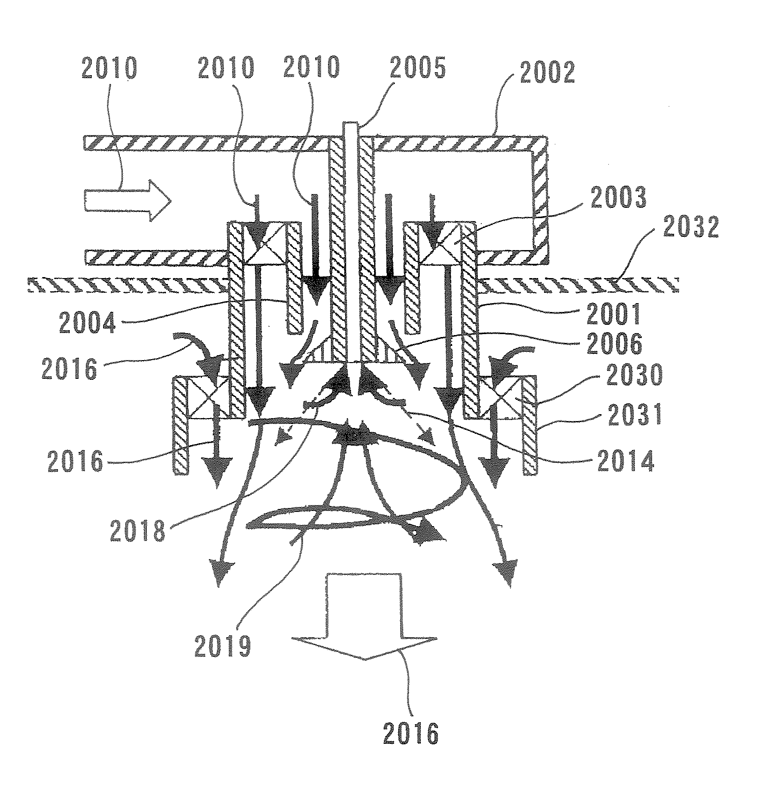
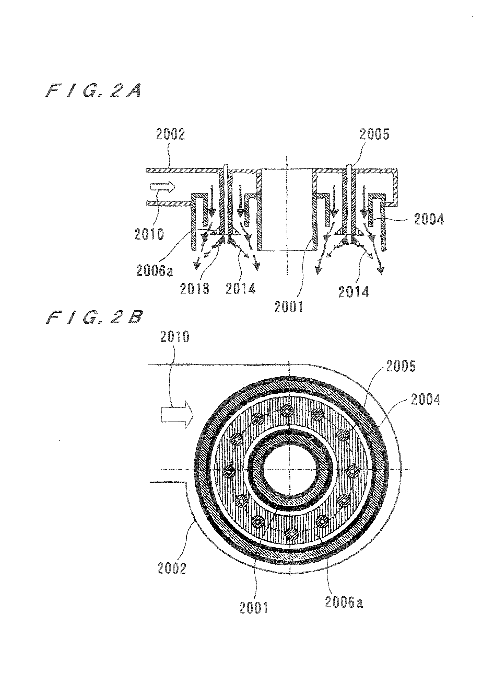
[0104]First, a combustion apparatus will be described with reference to FIGS. 5 and 6. The combustion apparatus shown in FIG. 5 has an annular container 12 with one end (close end) 10 which is closed, an inflow casing 14, a swirler 16, and a fuel nozzle 18 provided on a rear face of the upper end (close end) 10 of the annular container 12. A plurality of air inflow portions 20 are formed at common pitches on a side surface of a peripheral portion (outer cylindrical portion 13 described below) of the annular container 12. Combustion air 22 flows through the air inflow portions 20 into the interior of the annular container 12, and inflow passages are formed by the air inflow portions 20, the inflow casing 14, and the swirler 16.
[0105]As shown in FIG. 6 in detail, the annular container 12 has an inner cylindrical portion 15 and an outer cylindrical portion 13, and is configured such that the inner cylindrical portion 15 and the outer cylindrical portion 13 are closed by the close end ...
second embodiment
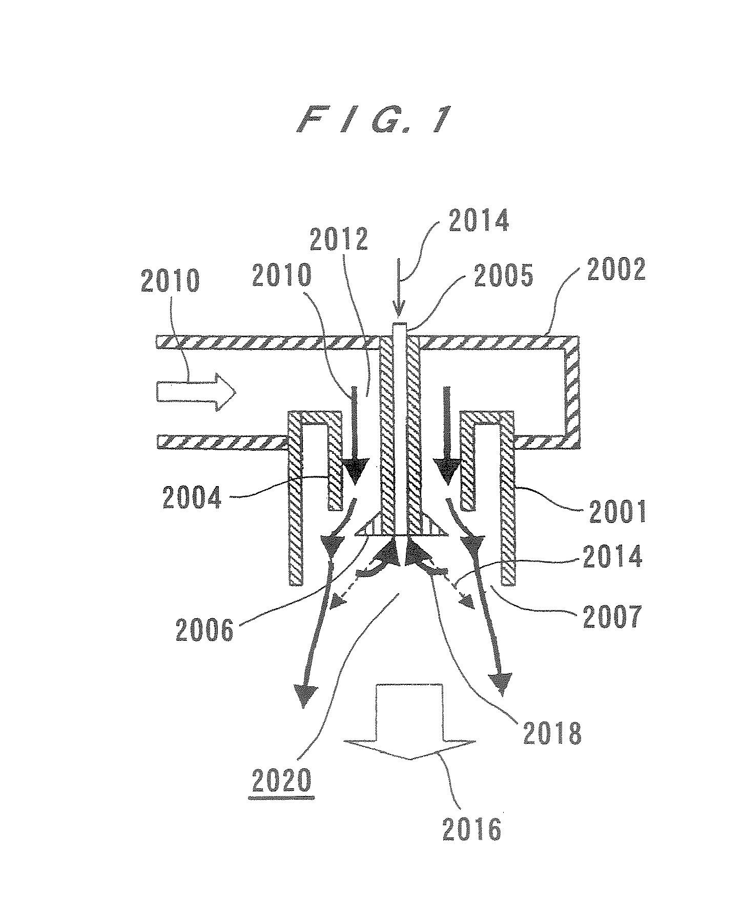
[0117] thus constructed, combustion air 22 flows from the air inflow portions 20 into the annular container 112 so as to form a swirling flow 28 having a larger velocity component in a direction opposite to an outlet 26. Specifically, the air 22 flowing into the annular container 112 forms a flow 28 having a velocity component in a direction of a central axis J of the annular container 112 from the open end 26 to a close end 110 and a velocity component to swirl in a circumferential direction.
[0118]Simultaneously, fuel 23 is injected toward the air inflow portions 20 (inflow passages) with a velocity component in the direction of the central axis J from the close end 10 to the open end 26 and a velocity component directed radially outward.
[0119]In FIGS. 7 and 8, the cross-section change portion 100 of the outer cylindrical portion 113 in the annular container 112 is illustrated as being perpendicular to the axial direction of the annular container 112. However, the cross-section cha...
third embodiment
[0123] shown in FIGS. 9 and 10, since a combustion chamber is formed by the annular container 212, the secondary cylinder 200, and the connecting member 270, the combustion apparatus can readily be assembled.
[0124]In the third embodiment, air flowing from the inflow portions 20 into the annular container 212 forms a flow 28 having a velocity component in a direction of a central axis J of the annular container 212 from the open end 26 to the close end 210 and a velocity component to swirl in a circumferential direction of the annular container 212. Simultaneously, fuel is injected toward the inflow portions 20 (inflow passages) with a velocity component in the direction of the central axis J from the close end 210 to the open end 26 and a velocity component directed radially outward.
[0125]The third embodiment shown in FIGS. 9 and 10 is configured so as to provide auxiliary air inflow ports 271 (additional inflow passage) on an inner side of the close end 210 near the inner cylindric...
PUM
 Abstract
Description
Claims
Application Information