Engineered Scaffolds for Intervertebral Disc Repair and Regeneration and for Articulating Joint Repair and Regeneration

a technology of intervertebral discs and engineering scaffolds, applied in the field of biomaterial scaffolds, can solve the problems of inability to design scaffolds, subject to wear and fatigue problems of synthetic materials, etc., and achieve the effect of controlling geometric thickness and achieving effective mechanical and mass transport properties

Active Publication Date: 2008-08-14
RGT UNIV OF MICHIGAN +1
View PDF33 Cites 74 Cited by
  • Summary
  • Abstract
  • Description
  • Claims
  • Application Information

AI Technical Summary

Benefits of technology

[0012]Advantages of the method of the invention include the ability to create designed microstructures that can mimic intervertebral load carrying capability, to provide directed nutrients to seeded/migrated cells in the disc, and the capability of creating disc structures that can regrow natural tissue. This provides a potential advantage over artificial discs, which as synthetic materials are subject to wear and fatigue failure. Regrowth of a new disc would provide a natural tissue that could remodel in response to applied loads and would be subject to the wear and fatigue problems of synthetic materials. In addition, the capability of creating designed scaffolding would provide the necessary load bearing capability via designed elasticity and permeability for tissue engineering an intervertebral disc that non-designed scaffolds coul

Problems solved by technology

Regrowth of a new disc would provide a natural tissue that could remodel in response to applied loads and would be subject to the wear and fatigue problems of synthetic materials.
In addition, the capability of cr

Method used


Image

  • Engineered Scaffolds for Intervertebral Disc Repair and Regeneration and for Articulating Joint Repair and Regeneration
  • Engineered Scaffolds for Intervertebral Disc Repair and Regeneration and for Articulating Joint Repair and Regeneration
  • Engineered Scaffolds for Intervertebral Disc Repair and Regeneration and for Articulating Joint Repair and Regeneration

Examples


Embodiment Construction

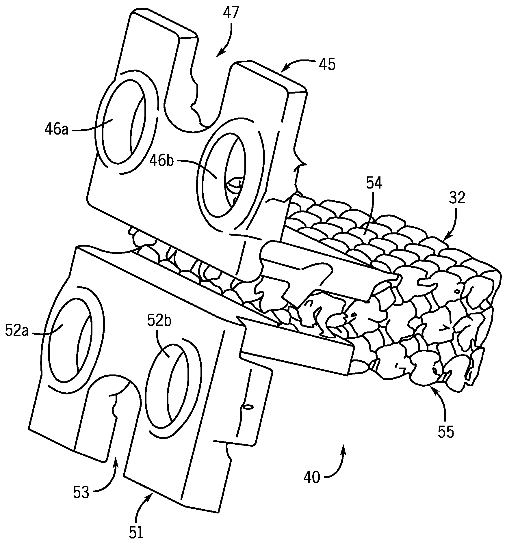
[0047]An intervertebral disc scaffolding according to the invention includes: (i) a designed porous microstructured scaffolding itself, made from biodegradable polymers (e.g., polycaprolactone), biodegradable ceramics (e.g., calcium phosphate), or non-biodegradable metals or metal alloys (e.g., titanium or titanium alloys), or mixtures thereof, and (ii) fixation structures for integrating the designed intervertebral scaffolding to the adjacent vertebrae. As used herein, a “biodegradable” material is one which decomposes under normal in vivo physiological conditions into components which can be metabolized or excreted.

[0048]The scaffolding may include a bioactive agent at any desired location in the scaffold. A “bioactive agent” as used herein includes, without limitation, physiologically or pharmacologically active substances that act locally or systemically in the body. A bioactive agent is a substance used for the treatment, prevention, diagnosis, cure or mitigation of disease or ...


PUM

PropertyMeasurementUnit
Microstructureaaaaaaaaaa
Mechanical propertiesaaaaaaaaaa
Permeabilityaaaaaaaaaa

Abstract

Methods for the engineering and preparation of intervertebral disc repair scaffolds and articulating joint repair scaffolds are disclosed. The methodology utilizes either magnetic resonance images or combined magnetic resonance and computed tomography images as a template for creating either the intervertebral scaffold or the joint repair scaffold (e.g., osteochondral scaffold) with fixation to the underlying bone. The disc scaffold design may include an outer annulus that may contain desired structures and a central nucleus pulposus region that could either contain a designed microstructure or a contained hydrogel. The osteochondral scaffold may include a bone compartment interface with a cartilage compartment. The bone compartment may interface with a cutout portion of the bone through fixation components. Different microstructure designs may be created for the bone and cartilage compartment to represent desired mechanical and mass transport properties. The scaffolds are designed with a microstructure that controls elastic and permeability property distribution within the scaffold.

Description

CROSS-REFERENCES TO RELATED APPLICATIONS[0001]This application claims priority from U.S. Provisional Patent Application No. 60 / 855,234 filed Oct. 30, 2006.STATEMENT REGARDING FEDERALLY SPONSORED RESEARCH[0002]This invention was made with government support under grant number R01 DE 13608 awarded by the National Institutes of Health. The government has certain rights in the invention.BACKGROUND OF THE INVENTION[0003]1. Field of the Invention[0004]This invention relates to biomaterial scaffolds, and more particularly to biomaterial scaffolds for intervertebral disc repair and / or regeneration and biomaterial scaffolds for articulating joint repair and / or regeneration.[0005]2. Description of the Related Art[0006]It is reported in U.S. Patent Application Publication No. 2003 / 0069718 and corresponding U.S. Pat. No. 7,174,282 that biomaterial scaffolds for tissue engineering perform three primary functions. The first is to provide a temporary function (stiffness, strength, diffusion, and p...

Claims


Application Information

Patent Timeline
IPC IPC(8): A61F2/44G06G7/60
CPCA61F2310/00796A61F2310/00293A61F2/28A61F2/2846A61F2/30767A61F2/30942A61F2/3662A61F2/389A61F2/442A61F2002/2817A61F2002/30004A61F2002/30014A61F2002/30034A61F2002/30062A61F2002/3008A61F2002/30224A61F2002/30271A61F2002/30578A61F2002/30599A61F2002/30604A61F2002/30616A61F2002/30761A61F2002/30777A61F2002/30785A61F2002/30789A61F2002/30838A61F2002/30841A61F2002/30884A61F2002/30892A61F2002/3092A61F2002/30948A61F2002/30962A61F2002/30968A61F2002/3097A61F2002/30991A61F2210/0004A61F2230/0069A61F2230/0082A61F2250/0014A61F2250/0018A61F2250/0031A61F2250/0063A61F2250/0098A61F2310/00017A61F2310/00023A61F2310/00029A61F2310/00976B33Y80/00B33Y50/00A61F2002/30032A61F2002/30261A61F2002/30593A61P19/08
Inventor LIN, CHIA-YINGLAMARCA, FRANKFEINBERG, STEPHEN E.MURPHY, WILLIAM L.ADOX, JAMES R.HOLLISTER, SCOTT J.
Owner RGT UNIV OF MICHIGAN
Why Eureka
Try Eureka