Electric Motor and Transmission Drive Unit For Actuators In A Motor Vehicle

a technology of transmission drive and actuator, which is applied in the direction of gearing details, mechanical equipment, manufacturing tools, etc., can solve the problem that the open electric motor that is used is not suited for use without a transmission housing

Inactive Publication Date: 2008-08-21
ROBERT BOSCH GMBH
View PDF7 Cites 29 Cited by
  • Summary
  • Abstract
  • Description
  • Claims
  • Application Information

AI Technical Summary

Problems solved by technology

For this reason, the open electric motor that is used is not suited for use without a transmission housing.

Method used


Image

  • Electric Motor and Transmission Drive Unit For Actuators In A Motor Vehicle
  • Electric Motor and Transmission Drive Unit For Actuators In A Motor Vehicle
  • Electric Motor and Transmission Drive Unit For Actuators In A Motor Vehicle

Examples


Embodiment Construction

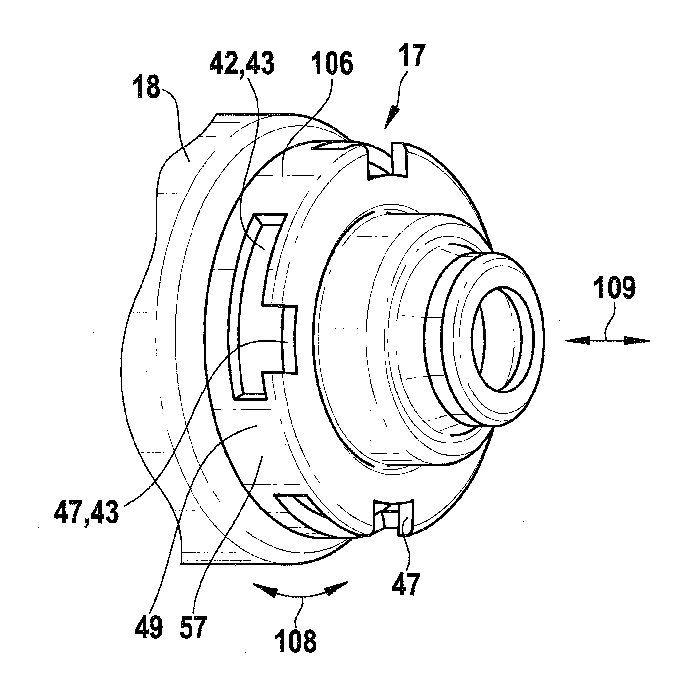
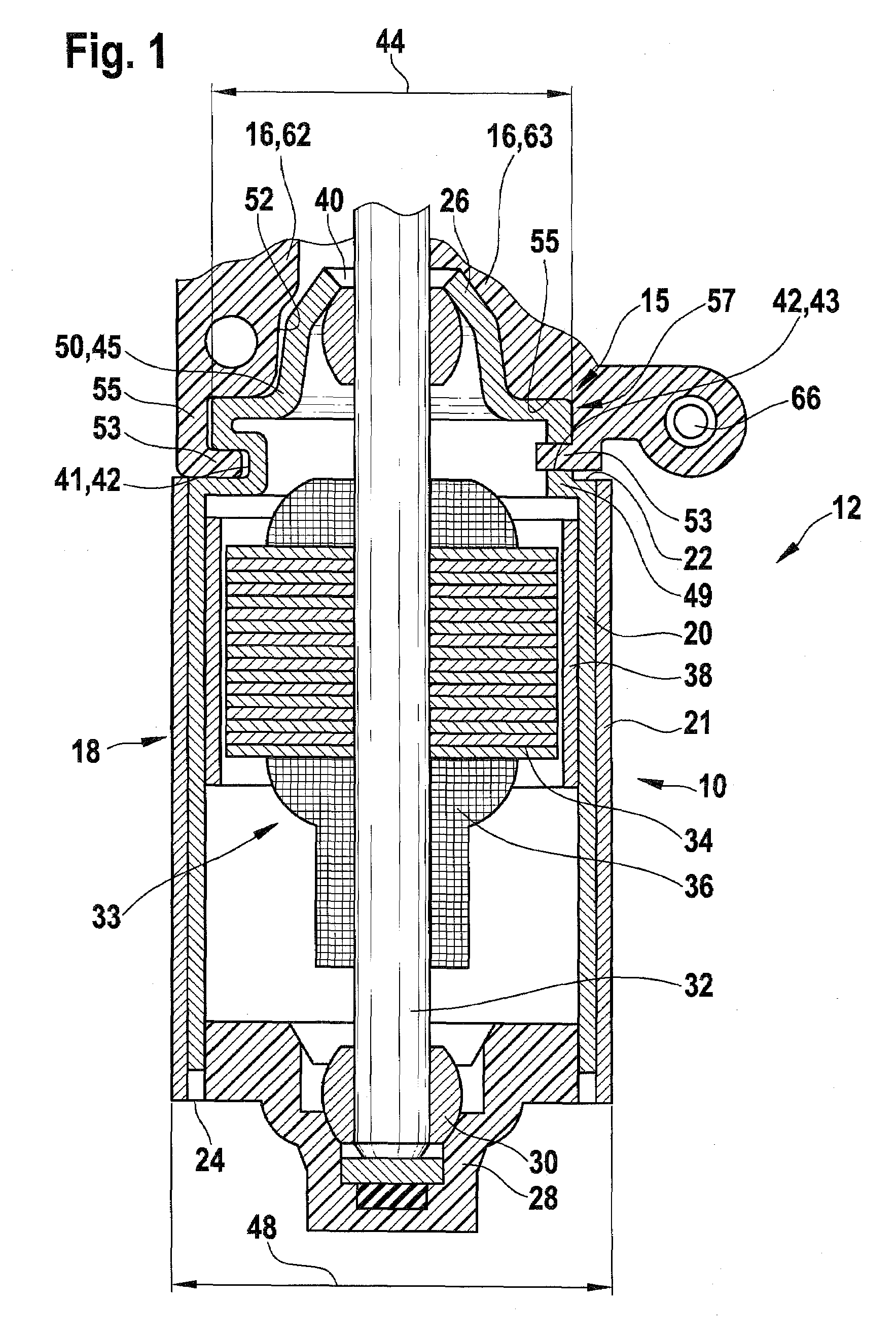
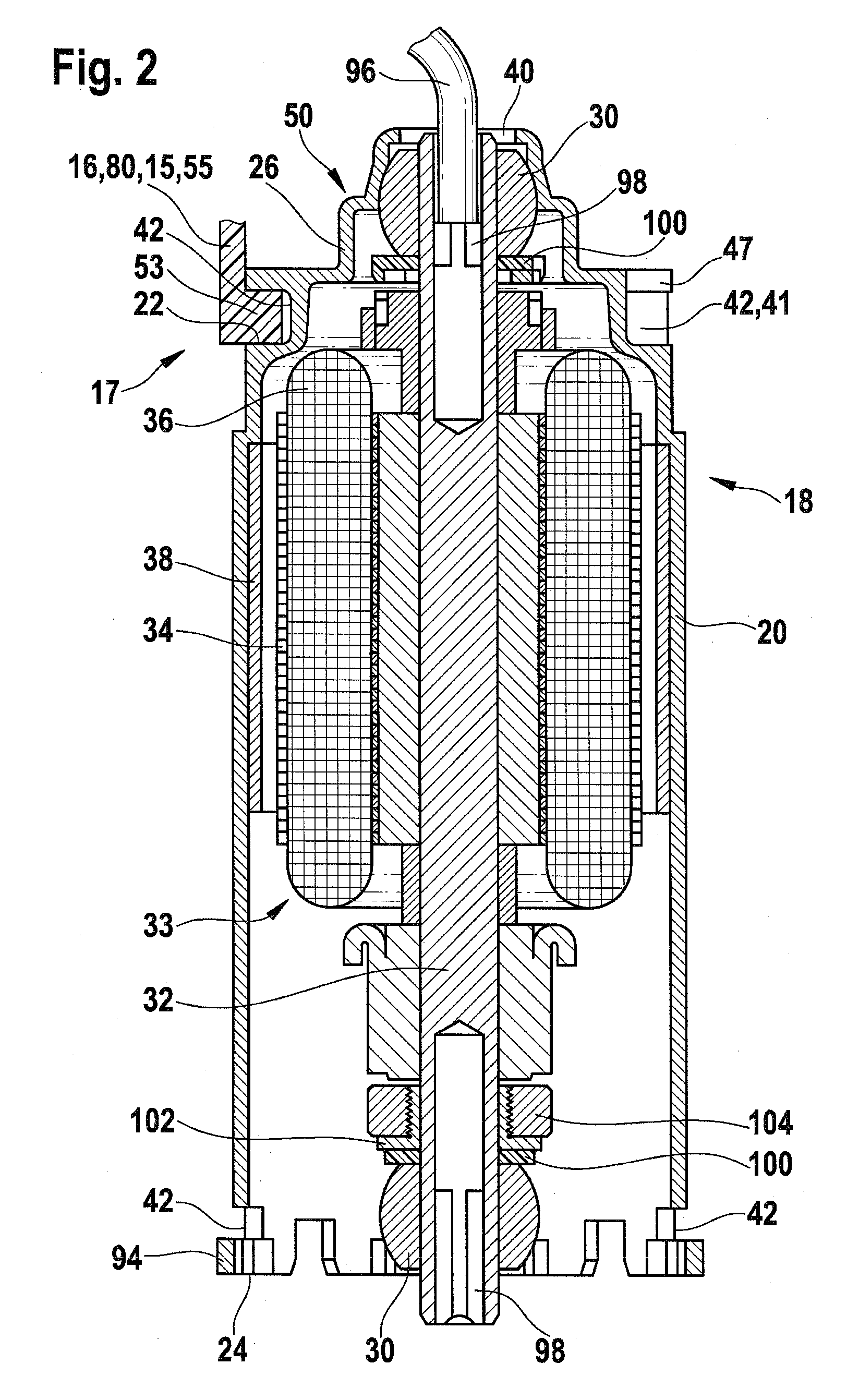
[0027]A transmission drive unit 12 is shown in FIG. 1, with which a separate electric motor 10 is connected with a partially-shown transmission interface 15 that is designed as transmission housing 16. Electric motor 10 includes a pole housing 18 with a pole housing jacket 20 and bearing covers 26, 28 integrally formed with its end faces 22, 24. Bearing covers 26, 28 accommodate bearings 30—which are designed as sliding bearings and, in particular, as calotte bearings in the exemplary embodiment—in which an armature 33 is supported via an armature shaft 32. An armature stack 34 with electrical windings 36 is located on armature shaft 32. Electrical windings 36 interact with permanent magnets 38 located on pole housing jacket 20. Armature shaft 32 passes through bearing cover 26 on end face 22 via a hole 40 located therein in the axial direction. Armature shaft 32 extends—with a not-shown driven element—into transmission element 16, in order to provide a drive torque for movable part...


PUM

PropertyMeasurementUnit
outer diameteraaaaaaaaaa
couple forceaaaaaaaaaa
weightaaaaaaaaaa

Abstract

The invention relates to an electric motor (10) and gearing/drive unit (12) for actuators in a motor vehicle, comprising an armature shaft (32) mounted inside a pole casing (18), which has a jacket (20) and, on at least one face (22, 24), a bearing cover (26, 28) for accommodating a bearing (30) for the armature shaft (32). At least one radial recess (42) is formed on the pole casing (18) that, after the complete assembly of the pole casing (18), is suited for the insertion of at least one radial fastening web (53) of a gearing interface (15) inside the pole casing (18) in order to fasten the electric motor (10) to the gearing interface (15). The invention also relates to a method for producing an inventive gearing/drive unit.

Description

RELATED ART[0001]The present invention relates to an electric motor and a transmission drive unit for use in adjustment devices in a motor vehicle, according to the preamble of independent Claims 1 and 13 and 18.[0002]Publication DE 100 19 512 A1 makes known a power window drive, the housing of which includes a pole pot and a housing that closes the pole pot. The housing that closes the pole pot is a transmission housing with an integrated electronics housing. A separate component—as a brush holder—is located between the two housing parts, and also serves as a seal between the two housing parts. The pole pot is composed of a deep-drawn, flattened cylindrical tube, on the open end of which a flange is integrally formed, in which holes are formed for receiving screws. Blind threads are formed in the flange of the transmission housing, into which the screws are turned, thereby fixedly connecting the two housing parts with each other. More recesses are formed in the flange of the pole p...

Claims


Application Information

Patent Timeline
Patent Type & Authority Applications(United States)
IPC IPC(8): H02K7/116F16H57/02
CPCH02K7/1166Y10T29/49947Y10T74/2186H02K7/116
Inventor OBERLE, HANS-JUERGENSCHEER, DIETERSCHWENDEMANN, FRANZBERNAUER, CHRISTOF
Owner ROBERT BOSCH GMBH
Why Eureka
Try Eureka