Solid Electrolytic Capacitor, Anode Used For Solid Electrolytic Capacitor, and Method of Manufacturing the Anode

a solid electrolytic capacitor and anode technology, applied in the direction of electrolytic capacitors, capacitor electrodes, liquid electrolytic capacitors, etc., can solve the problems that the capacitance of the solid electrolytic capacitor cannot be properly satisfied and the need for small size cannot be satisfied, and achieves the effect of high density, high density, and manufacturing properly and efficiently

Inactive Publication Date: 2008-08-21
ROHM CO LTD
View PDF5 Cites 6 Cited by
  • Summary
  • Abstract
  • Description
  • Claims
  • Application Information

AI Technical Summary

Benefits of technology

[0015]With this method, the solid electrolytic capacitor anode according to the first aspect of the present invention can be manufactured properly and efficiently. Particularly, to provide a high-density porous sintered body, it is preferable that the porous body therefor has a high-density and contains minute pores even after compressed with a large pressure, which may be realized by forming the porous body by using powder of an appropriate average particle size, for example. The porous body is not directly bonded to the metal plate. Therefore, the porous body does not need to have properties suitable for bonding to the metal plate. Therefore, the porous body can be formed to have a high density, so that the porous sintered body can have a high density. Further, the porous sintered body made from the bonding material does not need to have a very high density. Therefore, as the bonding material, it is possible to select a material which has a great affinity with both of the porous body and the metal plate and which can properly bond these parts together when heated.
[0016]According to a fourth aspect of the present invention, there is provided a method for manufacturing an anode for a solid electrolytic capacitor. The method comprises the steps of preparing a porous sintered body made of valve metal and a metal plate made of valve metal, and bonding the porous sintered body and the metal plate to each other by using a bonding material containing valve metal powder. Also with this method, the solid electrolytic capacitor anode according to the first aspect of the present invention can be manufactured properly and efficiently. Particularly, the porous sintered body is formed by e.g. sintering the porous body solely, and the porous body is bonded to the metal plate after it is sintered. By sintering the porous body solely in this way, such a problem that other parts are heated excessively does not occur even when heating is performed to a temperature suitable for obtaining a high-density porous sintered body. Moreover, in sintering the bonding material after the porous sintered body and the metal plate are bonded together, heating does not need to be performed to such a high temperature necessary for forming a high-density porous sintered body, which is advantageous for reducing the manufacturing cost.

Problems solved by technology

Therefore, in the anode X, the capacitance per unit volume of the porous sintered body 94 is not sufficiently high, so that the need for small size and large capacitance of the solid electrolytic capacitor cannot be properly satisfied.

Method used


Image

  • Solid Electrolytic Capacitor, Anode Used For Solid Electrolytic Capacitor, and Method of Manufacturing the Anode
  • Solid Electrolytic Capacitor, Anode Used For Solid Electrolytic Capacitor, and Method of Manufacturing the Anode
  • Solid Electrolytic Capacitor, Anode Used For Solid Electrolytic Capacitor, and Method of Manufacturing the Anode

Examples


first embodiment

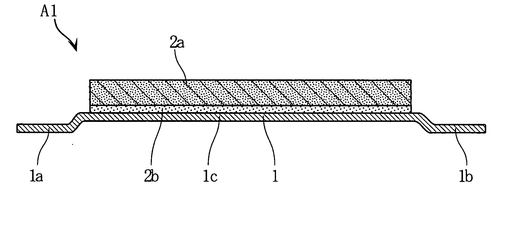
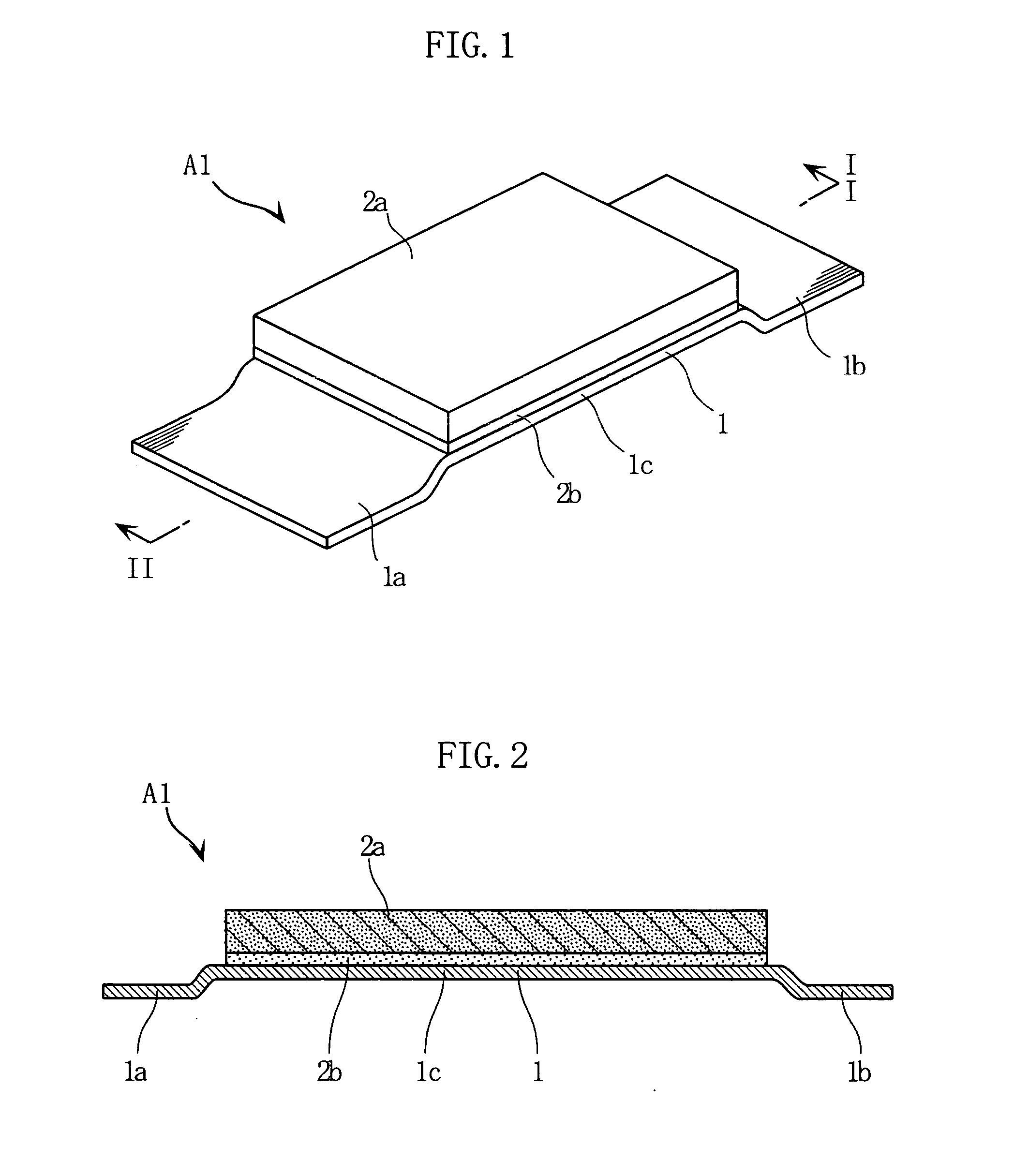
[0034]FIGS. 1 and 2 show an example of a solid electrolytic capacitor anode according to the present invention. The illustrated anode A1 includes an anode metal plate 1 and a first and a second porous sintered members 2a and 2b.

[0035]The first sintered member 2a is formed by compacting niobium powder, which is a metal material having valve action (valve metal), into a rectangular plate and then sintering the plate. The first sintered member 2a is provided on the anode metal plate 1 via the second sintered member 2b. As the material of the first sintered member 2a, any valve metal can be used, and tantalum may be used instead of niobium, for example. However, since niobium is superior to tantalum in flame retardancy, niobium is preferable as the material of the first sintered member 2a which produces heat in use.

[0036]The second sintered member 2b is provided between the first sintered member 2a and the anode metal plate 1. The second sintered member 2b is formed by sintering a bond...

second embodiment

[0050]With this structure, in e.g. transferring the anode A2, the sintered members 2a and 2b are prevented from hitting against the surrounding objects (“obstacles”). When the sintered member 2a (or 2b) hits against an obstacle, minute holes formed at an outer surface of the sintered member may be closed. In such a case, it is difficult to properly impregnate the sintered member 2a with a solution for forming a dielectric layer and a solid electrolytic layer, so that the dielectric layer and the solid electrolytic layer cannot be formed properly. A solid electrolytic capacitor utilizing such a defective anode has drawbacks such as insufficient capacity and large leakage current. According to the present invention, such drawbacks can be avoided, and a solid electrolytic capacitor can be manufactured properly.

[0051]FIGS. 12 and 13 show an example of solid electrolytic capacitor utilizing the above-described anode A2. It is to be noted that, in the illustration of FIGS. 12 and 13, the ...


PUM

PropertyMeasurementUnit
temperaturesaaaaaaaaaa
thicknessaaaaaaaaaa

Abstract

An electrode (A1) for a solid electrolytic capacitor includes a metal plate (1) made of valve metal, and a porous sintered body (2a, 2b) provided on the metal plate (1) and made of valve metal. The porous sintered body includes a first sintered member (2a), and a second sintered member (2b) intervening between the first sintered member (2a) and the metal plate (1). The first sintered member (2a) is greater in density than the second sintered member (2b).

Description

TECHNICAL FIELD[0001]The present invention relates to a solid electrolytic capacitor using a porous sintered body made of valve metal, and particularly relates to an anode used for such a solid electrolytic capacitor. The present invention also relates to a method for manufacturing such an anode.BACKGROUND ART[0002]An example of anode used for a solid electrolytic capacitor is disclosed in the Patent Document 1 described below. As shown in FIG. 15A of the present application, the conventional anode includes a metal plate 91 and a porous sintered body 94 formed on the metal plate. The metal plate 91 and the sintered body 94 are made of metal having valve action (hereinafter simply referred to as “valve metal”). As shown in FIG. 15B, the illustrated anode X is prepared by applying a material 93 containing valve metal powder 92 onto the metal plate 91 and then sintering the material 93. With this method, the sintered body 94 having a desired size in plan view and a relatively small thi...

Claims


Application Information

Patent Timeline
Patent Type & Authority Applications(United States)
IPC IPC(8): H01G9/04H01G9/00H01G9/052H01G9/08
CPCH01G9/04Y10T29/417H01G9/052H01G9/15
Inventor KURIYAMA, CHOJIRO
Owner ROHM CO LTD
Why Eureka
Try Eureka