Compact scanned electron-beam x-ray source

a x-ray source, electron beam technology, applied in the direction of x-ray tube target and convertor, x-ray tube gas control, nuclear engineering, etc., can solve the problems of large vacuum chamber itself, material and manufacturing costs increase, and undesirable aberrations, so as to reduce the volume of the device

Active Publication Date: 2008-08-21
L3 TECH INC
View PDF10 Cites 47 Cited by
  • Summary
  • Abstract
  • Description
  • Claims
  • Application Information

AI Technical Summary

Benefits of technology

[0010]The invention provides a compact scanned electron-beam x-ray source that has an electron beam that is propagated parallel to the target and swept across the target in response to a moving magnetic cross field. Rather than scanning the beam by deflecting it about a single point, the point of deflection is translated along the target length, dramatically reducing the volume of the device.
[0011]This scanning x-ray source may include a high-voltage electron gun with an optional grid for pulsing the beam on and off and controlling the current. An accelerator section and a focus coil serve to focus the emitted electrons into a tightly bunched electron beam. An ion-clearing electrode serves to remove ions from within the vacuum envelope of the electron gun. A linear drift tube is coupled to the electron gun and provides a path for transmission of the electron beam to a collector disposed at the end of the beam travel. An x-ray target is provided that extends along a side edge of the length of the drift tube. A vacuum window extends along a top edge of the drift tube adjacent to the target to define an x-ray scanning dimension. Optionally, the target can be liquid or forced-air cooled. A vacuum pump maintains a vacuum condition within the drift tube. A defocusing coil unfocuses the electron beam at the end of its travel within the drift tube so that it can be evenly distributed within the collector. Lastly, the drift tube may include interlocks to protect the tube, such as a sensor to prevent excessive target dwell time. The collector can be isolated to monitor beam current and additionally operated at depressed potential to recover beam energy. The focus and defocus coils, along with the bending magnet (or magnets), may be mounted outside the vacuum envelope. Multiple x-ray tubes may be deployed to obtain the angular coverage required by a particular application.
[0012]In one embodiment of a scanning electron-beam x-ray source in accordance with the present invention, a series of magnets are disposed along the length of the drift tube such that they can selectively induce a magnetic field in the drift tube perpendicular to the direction of travel of the electron beam. When a particular magnet is active, the resulting perpendicular magnetic field through the drift tube causes the electron beam to bend toward the heavy metal x-ray target. By controlling the amplitude and timing of the magnetic field produced by each of the magnets, it is possible to control the point at which the electron beam, propagating along the drift tube, will bend into the x-ray target. Thus, the electron beam can be scanned along the length of the heavy metal target. Because the deflection point moves along the length of the drift tube, the required size of the vacuum chamber remains relatively small, reducing the cost and complexity of the x-ray source.
[0014]In another embodiment in accordance with the present invention, the permanent magnet is mounted on a closed-loop track that is stretched around two pulleys. A drive pulley rotates, pulling a drive belt to which the permanent magnet is attached. As the drive belt draws the permanent magnet along the drift tube, the resulting magnetic field induced within the drift tube causes the point of deflection of the electron beam to move along the length of the drift tube, scanning the electron beam along the x-ray target. While this embodiment may require increased volume to implement, it has the advantage of potentially higher scan rates when compared to the more compact embodiment in which a permanent magnet is mounted to a sliding carriage on the drift tube itself.
[0015]In another embodiment of a scanning electron-beam-x-ray source in accordance with the present invention, an array of electromagnets is implemented along the length of the drift tube. By energizing one or more of the electromagnets, a magnetic field is induced within the drift tube sufficient to bend the electron beam into the x-ray target running along the side of the drift tube. By controlling the times at which individual elements of the electromagnet array are energized, any desired scanning profile can be created. This implementation has the advantage of potentially very high scan rates that may exceed those achievable with a mechanically scanned system.
[0017]In another embodiment of a scanned electron-beam x-ray source in accordance with the present invention, a pair of elongated polepieces extends along the length of the drift tube and is coupled to an electromagnet. The strength of the magnetic field extending through the drift tube varies as a function of the distance from the electromagnet. In one embodiment, the polepieces may be tapered to enhance the variation of the magnetic field along the length of the drift tube. By varying the amplitude of the current through the electromagnet, the location at which the field through the drift tube is strong enough to bend the electron beam into the target can be varied. Thus, ramping the current through the electromagnet causes the deflection point of the electron beam to scan along the length of the drift tube, creating a scanning x-ray beam, originating at the moving point at which the electron beam strikes the target.

Problems solved by technology

However, because the electron beam must propagate through a vacuum between the deflection coil and the x-ray target, it is necessary that the vacuum chamber itself be quite large.
Furthermore, it is often necessary to limit the maximum deflection angle of the electron beam because the large magnetic fields required to produce large deflection angles can result in aberrations that are undesirable for many applications.
As the size and complexity of vacuum systems increase, material and manufacturing costs rise, and reliability can be negatively impacted.

Method used


Image

  • Compact scanned electron-beam x-ray source
  • Compact scanned electron-beam x-ray source
  • Compact scanned electron-beam x-ray source

Examples


Embodiment Construction

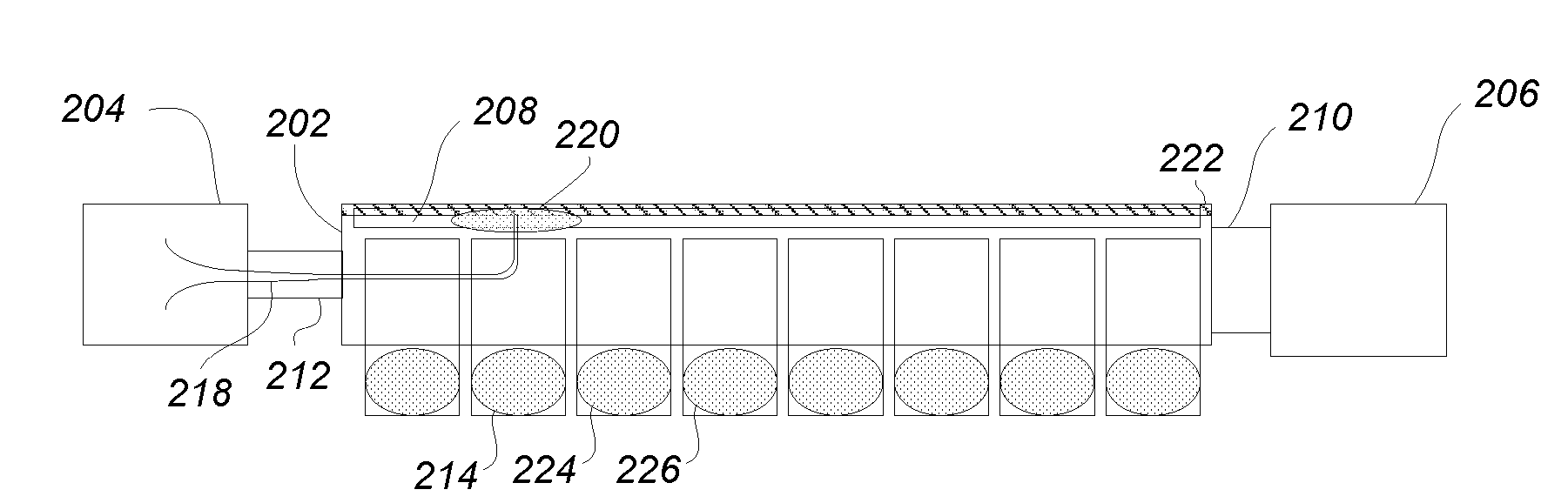
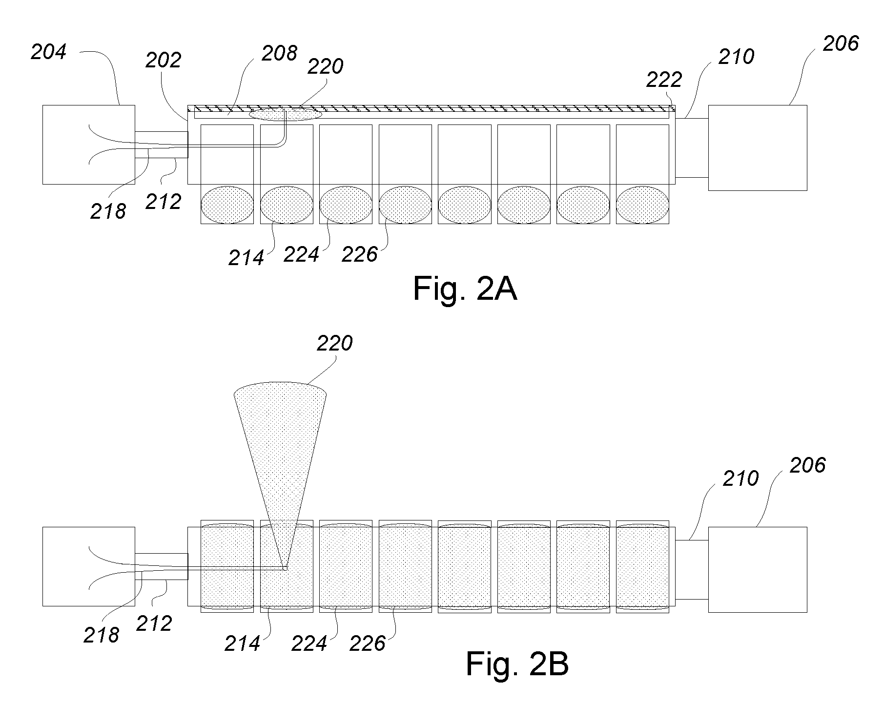
[0036]The invention provides a compact, reliable and low-cost scanning x-ray source that comprises an electron beam that is propagated parallel to the target and swept across the target in response to a moving magnetic cross field. Rather than scanning the beam by deflecting it about a single point, the point of deflection is translated along the target length, dramatically reducing the volume of the device. In the detailed description that follows, like element numerals are used to indicate like elements appearing in one or more of the figures.

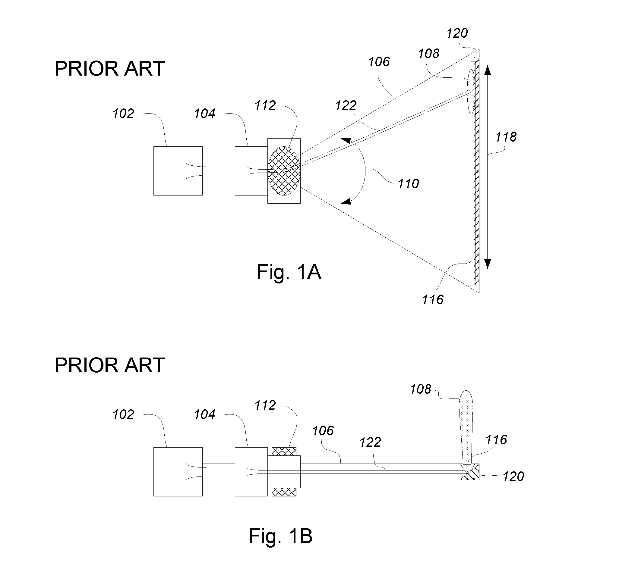
[0037]FIGS. 1A and 1B illustrate a conventional scanned electron-beam x-ray source. FIG. 1A provides a plan view, and FIG. 1B depicts an elevation view. An electron gun 102 produces an electron beam 122 that passes through a focus coil 104 that compresses the beam 122 to a small diameter. A large vacuum chamber 106 is located downstream of the focus coil 104. The vacuum chamber 106 has a tapered width such that it is narrow at a proximal end ...


PUM


Abstract

A compact, reliable scanning electron-beam x-ray source achieves reduced complexity and cost. In particular, the x-ray source includes an electron beam that is propagated parallel to an x-ray target and is swept across the target in response to a moving magnetic cross field. Rather than scanning the beam by deflecting it about a single point, the point of deflection is translated along the target length, dramatically reducing the volume of the device. The magnetic cross field is translated along the target length using either mechanical systems to move permanent magnets, or electrical systems to energize an array of electromagnets.

Description

RELATED APPLICATIONS[0001]This application claims the benefit under 35 U.S.C. § 119(e) of U.S. Provisional Application Ser. No. 60 / 890,986, entitled COMPACT SCANNED ELECTRON-BEAM X-RAY SOURCE, filed Feb. 21, 2007.BACKGROUND OF THE INVENTION[0002]1. Field of the Invention[0003]The present invention relates to high-energy electron beams, and more particularly, to a scanned electron-beam x-ray source suitable for computed tomography (CT) imaging systems, such as those used in medical and security applications, and for photon backscattering devices, such as those used for subsurface and through-wall detection.[0004]2. Description of Related Art[0005]It is well known in the art to use a high-energy electron beam to generate x-rays. When high-energy electrons strike a metal of high atomic number, their kinetic energy is converted to x-rays. This principle is employed in x-ray vacuum tubes, which typically use a thermionic cathode to emit electrons, and then form the electrons into a high-...

Claims


Application Information

Patent Timeline
Patent Type & Authority Applications(United States)
IPC IPC(8): H01J35/00
CPCG21K1/093H01J35/16H01J2235/20H01J2235/086H01J35/30
Inventor KIRSHNER, MARK FREDERICKWILSEN, CRAIG BISSETKOWALCZYK, RICHARD DONALD
Owner L3 TECH INC
Why Eureka
Try Eureka