
Machining Template Based Computer-Aided Design and Manufacture Of An Aerospace Component

a computer-aided design and aerospace technology, applied in the direction of program control, total factory control, instruments, etc., can solve the problems of increasing the mass of the component, complicated and time-consuming design of the aircraft component, and significant time delays, so as to facilitate the alteration of the computer model

Inactive Publication Date: 2008-08-21
AIRBUS OPERATIONS LTD
View PDF19 Cites 23 Cited by
  • Summary
  • Abstract
  • Description
  • Claims
  • Application Information

AI Technical Summary

Benefits of technology

[0013]Thus, as a result of the designing of the shape of the component comprising the use of templates that include machining data, there is no need for a separate step of generating manufacturing geometry and as such NC programming may be effected more efficiently. As such, the design of a component up to and including producing an appropriate NC program may be effected faster and can be automated to a greater degree than previously achievable with methods of the prior art. Also, the templates may effectively restrict the designing of the shape of the component so as to reduce or avoid the risk of designing a shape of component that is not possible to manufacture with a given machine and tool set. Thus, machining limitations may effectively be taken into account during the design process. The templates may for example include check-rules. Such check-rules may be arranged to ensure that conflicts do not occur, for example conflicts that would otherwise give rise to errors in the computer model, the manufacture or the NC programming of the component.
[0029]The component is preferably treated in a modular manner. The method may for example include dividing the component into sub-modules and then performing the method in relation to each such sub-module. Such a modular treatment can assist in the formation of a sufficiently detailed database of templates and facilitates the use of object-oriented design.

Problems solved by technology

The designing of aircraft components can be complicated and time-consuming even with the assistance of Computer Aided Design and Computer Aided Manufacture (CAD / CAM) systems.
One factor that introduces significant time delays is the necessity to covert the complicated geometry that defines the shape of a component into commands passable by a machine for manufacturing the component.
NC programming of a component can require the shape of the component to be manufactured to differ slightly from the shape of the component as designed in CAD as a result of the limitations of the manufacturing processes to be used.
Such changes are usually able to be made without affecting the functional performance of the component, but may sometimes have such an effect, which may require redesigning aspects of the component.
Also, such changes can impact the design of other parts of an assembly, of which the component forms only a part, especially other parts that are required to interface directly with the component.
Also, such changes often lead to an increase in the mass of the component, which in aircraft design is particularly undesirable.

Method used


Image

  • Machining Template Based Computer-Aided Design and Manufacture Of An Aerospace Component
  • Machining Template Based Computer-Aided Design and Manufacture Of An Aerospace Component
  • Machining Template Based Computer-Aided Design and Manufacture Of An Aerospace Component

Examples


Embodiment Construction

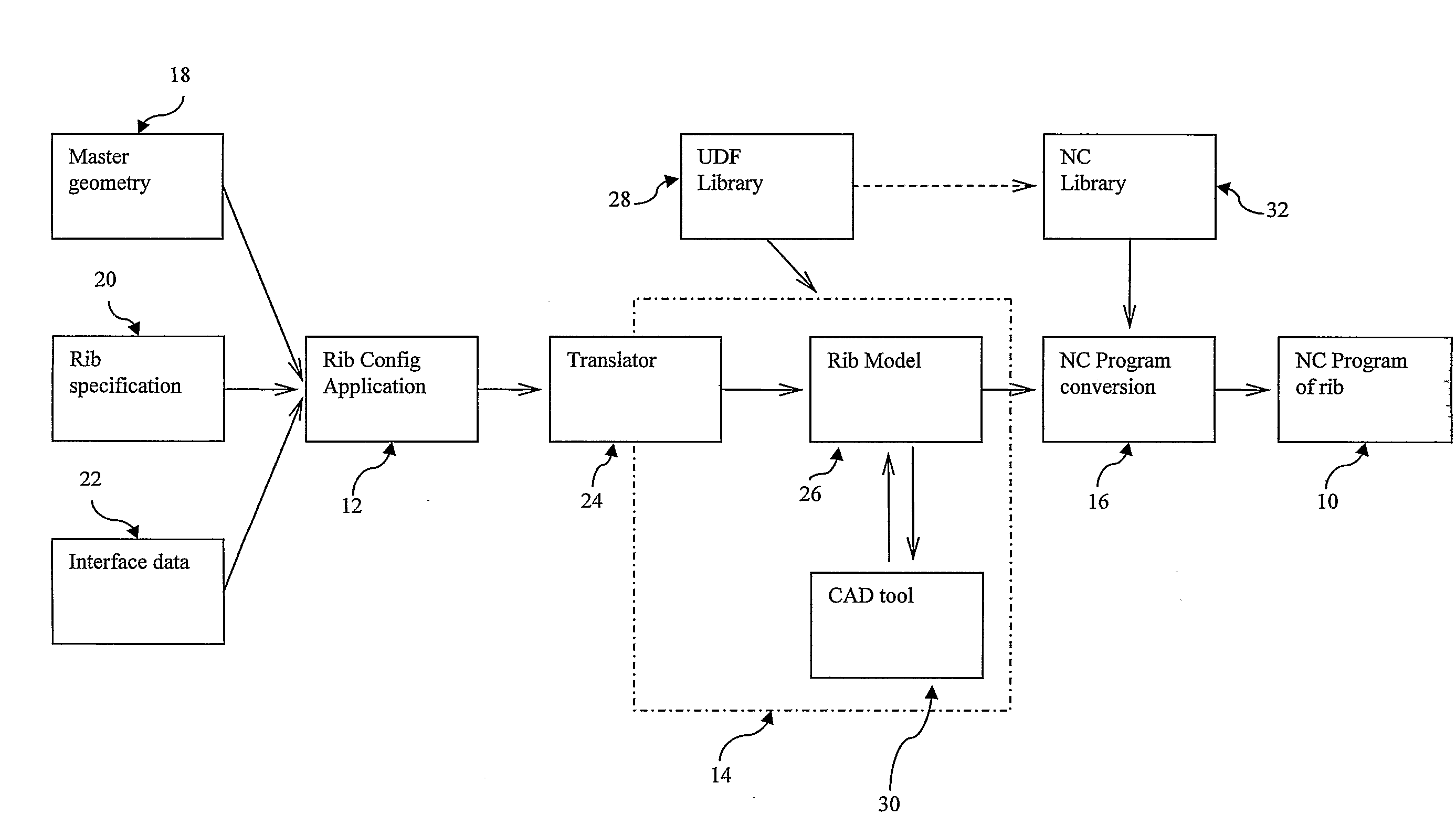
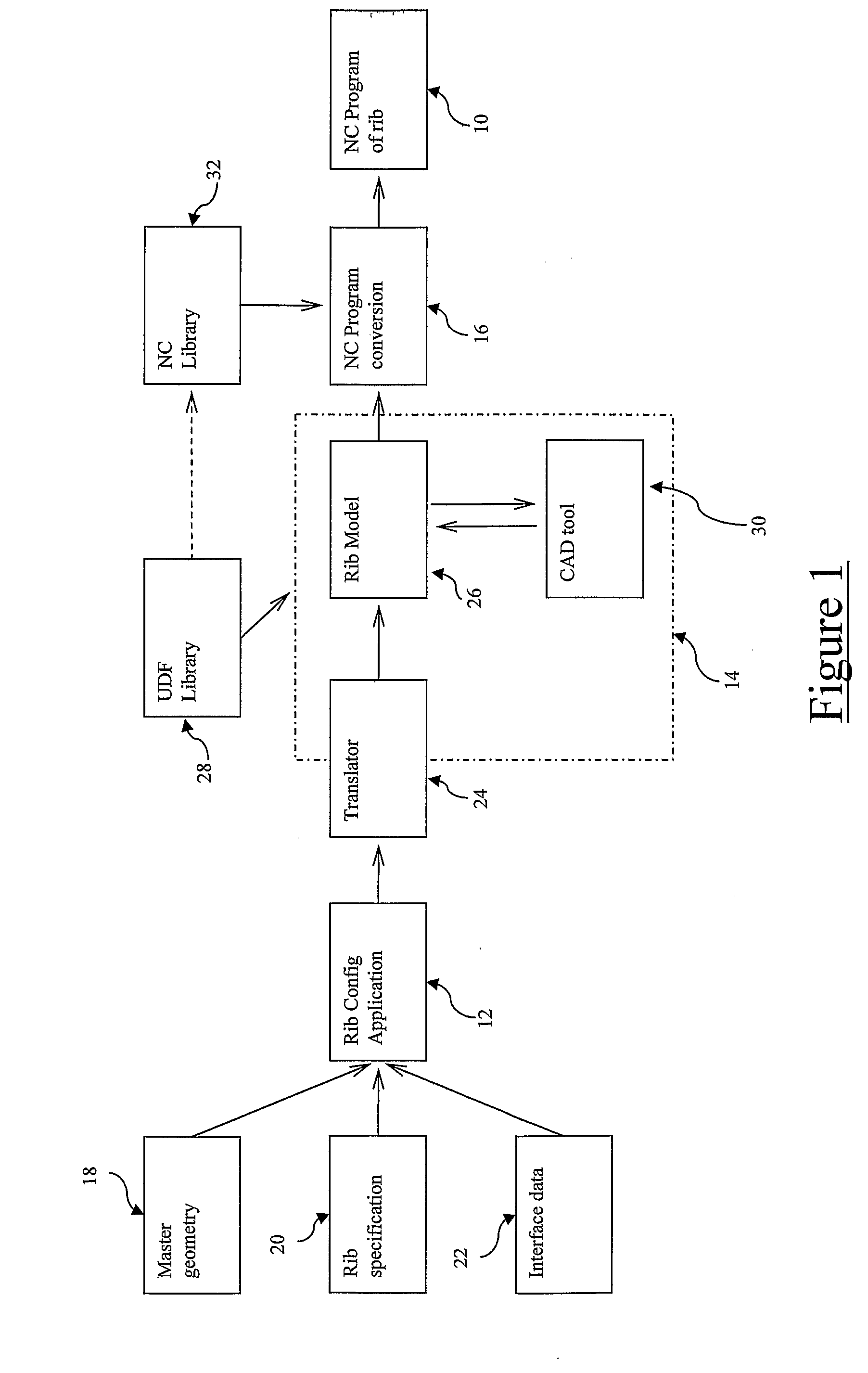
[0066]FIG. 1 shows a schematic overview of the processes and data used for generating an NC (numeric control) program 10 for machining a rib for an aircraft wing-box in accordance with an embodiment of the invention. The processes represented in FIG. 1 can be divided into three software modules, namely a rib configuration application module 12, a CAD system module 14, which allows an operator to manipulate the preliminary model of the rib to produce a detailed computer-model of the rib (including details of the final desired shape of the rib) and an NC programming module 16, which converts the detailed computer-model of the rib into an output in the form of a complete NC program 10 for manufacturing the rib.

[0067]The rib configuration module 12 is implemented by means of a KBE (knowledge-based engineering) CAD package named ICAD available from the French company Dassault Systèmes (the software originally being developed by Knowledge Technologies International also known as KTI). The...


PUM


Abstract

A CAD model of a component is designed by means of a CAD system that modifies the shape of the design of the component represented by the CAD model by means of templates held in a database of templates. The templates include machining data concerning the machining actions necessary to effect the alteration, represented by the template, of the shape of a work-piece. The CAD system outputs a computer model of the component comprising not only part geometry data concerning the shape of the component but also machining geometry data concerning the machining actions necessary for manufacturing from a work-piece a component having a shape in accordance with the outputted model of the component. This outputted computer model is then converted into an NC (numeric control) program by means of an NC program conversion module, by extracting NC code sequences from a database, the NC code sequences extracted corresponding to the templates of the UDF library used to design the shape of the CAD model.

Description

BACKGROUND OF THE INVENTION[0001]The present invention relates to the computer-aided design of a component, and in particular to the computer-aided design and manufacture of an aircraft component.[0002]The designing of aircraft components can be complicated and time-consuming even with the assistance of Computer Aided Design and Computer Aided Manufacture (CAD / CAM) systems. One factor that introduces significant time delays is the necessity to covert the complicated geometry that defines the shape of a component into commands passable by a machine for manufacturing the component. For example, a rib for use in an aircraft wing may have a shape defined by means of CAD data structures that then needs to be converted into numerical control (NC) codes for use by a 5-axis milling machine that, during manufacture of the component, effect movements of the milling machine to machine away material from a solid metal billet to produce the shape of the rib. Such a process is called NC programmi...

Claims


Application Information

Patent Timeline
Patent Type & Authority Applications(United States)
IPC IPC(8): G06F17/50G05B19/18G06F7/00G06F17/30G05B19/4097
CPCG05B19/4097G05B2219/35066G06F2217/12G05B2219/35216G06F17/5095G05B2219/35081G06F2119/18G06F30/15Y02P90/02
Inventor CREW, DARREN PAULMALCOLM, COLIN
Owner AIRBUS OPERATIONS LTD
Learn More