Network design method and system therefor

Inactive Publication Date: 2008-08-21
IBWAVE SOLUTIONS
View PDF9 Cites 14 Cited by
  • Summary
  • Abstract
  • Description
  • Claims
  • Application Information

AI Technical Summary

Benefits of technology

[0015]The present invention reduces the difficulties and disadvantages of the prior art by providing a software, and a computer system thereof, which enables the wireless designer to use a single design tool to design a network, adjust the para

Problems solved by technology

With the new form factor of cellular phones and the growing demand for wireless data services, the mobile traffic has generally shifted from outdoors to indoors, where typically Radio Frequency (RF) penetration is often limited.
In-building RF design is generally very complex, especially nowadays with the advent of multi-carriers and multi-technologies that are requested by the building's owners.
These systems can cause serious deterioration of the network if they are not engineered correctly.
Moreover, wireless operators may suffer from a lack of knowledge and expertise and may not take full advantage of their in-building networks.
Nevertheless, the aforesaid methods and systems generally only perform the prediction part of a network design.
These methods tend to be error prone, complicated and not standard from one designer to another.
When the designer chooses

Method used


Image

  • Network design method and system therefor
  • Network design method and system therefor
  • Network design method and system therefor

Examples


Embodiment Construction

[0062]A novel network design method and its associated computer system will be described hereinafter. Although the invention is described in terms of specific illustrative embodiments, it is to be understood that the embodiments described herein are by way of example only and that the scope of the invention is not intended to be limited thereby.

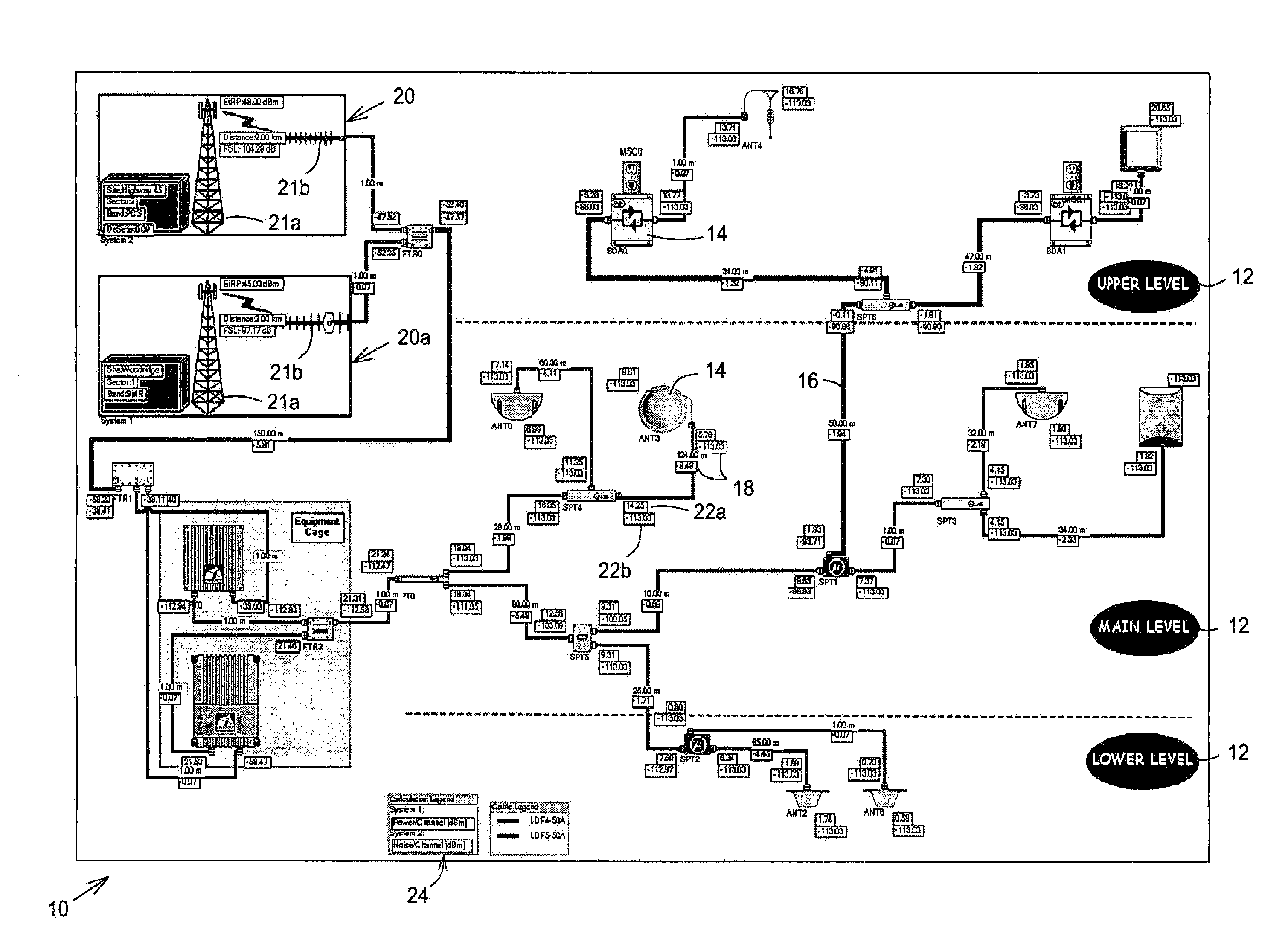
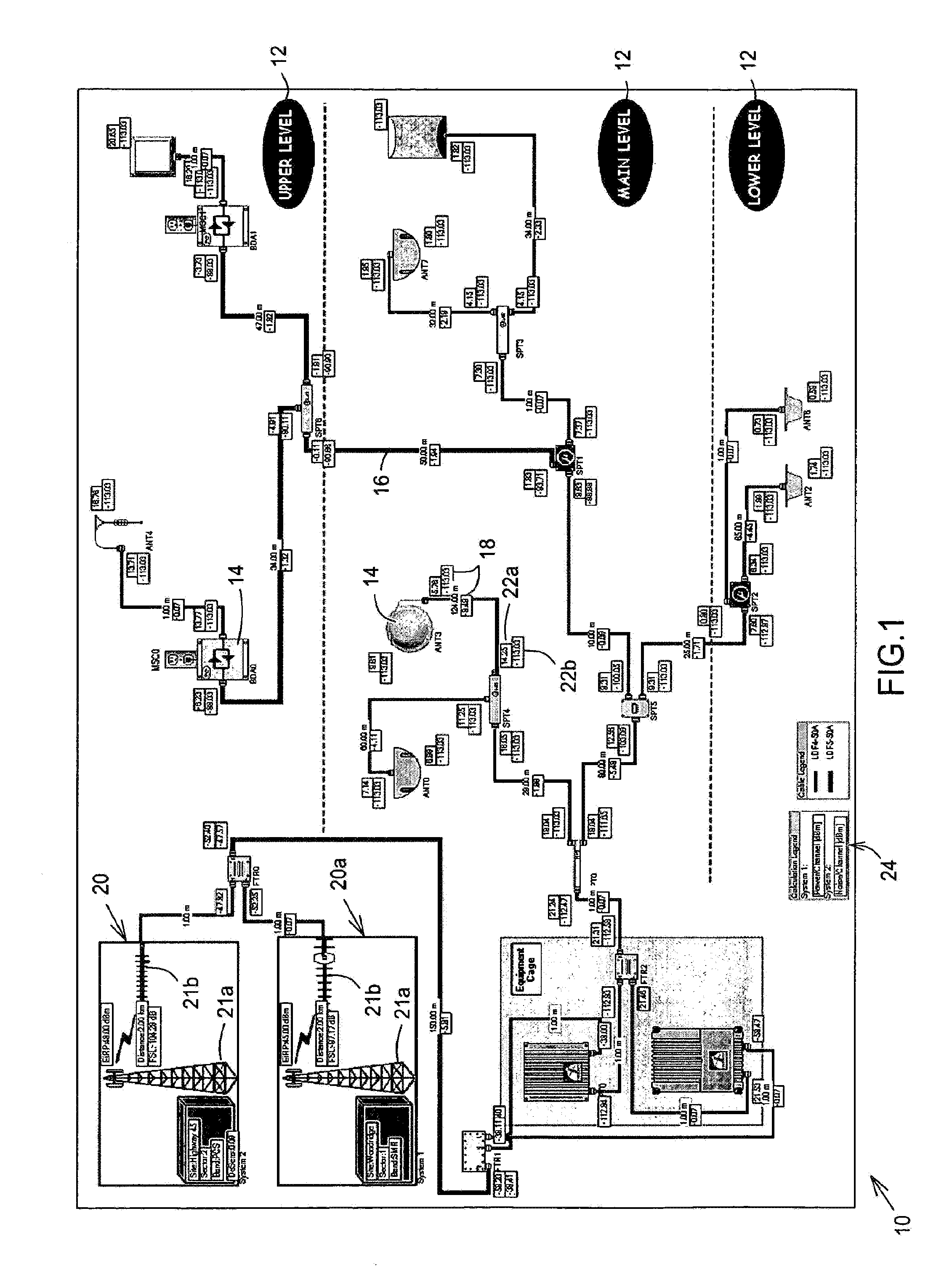
[0063]According to the preferred embodiment of the present invention, there is provided a computer-implemented method for creating a distributed antenna network (hereinafter “DAN”), as illustrated in FIG. 1, for use in designing preferably but not exclusively in-building wireless communications network.

[0064]The method of the present invention is understandably embodied in a software, stored on a computer-readable media which is run on a computer system. Computer systems are known in the art and therefore only the required computer devices will be recited. In any case, the skilled addressee will know which computer system and computer periphe...


PUM


Abstract

A computer-implemented method is disclosed for creating a distributed antenna network for use in designing a generally wireless communications network. The method includes the placing and interconnecting, on a design screen canvas, of network components, selected from a components database stored in a computer system, with several signal source systems having different parameters. The method also generally includes the verification of the compatibility of the different interconnected components and signal sources and the notification of incompatibility if any. The method further generally includes the calculation, at each interconnection, of the uplink and the downlink link budgets for each signal source. The method also includes the displaying of graphical representations of the estimated propagation of the signals according to the parameters of each signal source. A computer system for supporting the method is also disclosed.

Description

CROSS-REFERENCE TO RELATED APPLICATIONS[0001]The present patent application claims the benefits of commonly assigned U.S. patent application Ser. No. 10 / 744,018, filed on Dec. 24, 2003 and entitled “System and Method for Designing a Communications Network” and which is incorporated herein by reference.FIELD OF THE INVENTION[0002]The present invention concerns wireless communications networks, and more particularly system and method for designing a wireless communications network.BACKGROUND OF THE INVENTION[0003]Mobile communications devices, such as cellular telephones, pagers and the like, are now commonplace and are now being used almost more indoor than in vehicles. With the new form factor of cellular phones and the growing demand for wireless data services, the mobile traffic has generally shifted from outdoors to indoors, where typically Radio Frequency (RF) penetration is often limited. To maximize average revenues per users, reduce the percentage number of deactivations and ...

Claims


Application Information

Patent Timeline
IPC IPC(8): G06F17/50
CPCG06F17/50G06F2217/74G06F2217/36G06F2113/16G06F2111/12G06F30/00
Inventor BOUCHARD, MARIOCHARBONNEAU, HUGO
Owner IBWAVE SOLUTIONS
Why Eureka
Try Eureka