Fully differential amplifier with continuous-time offset reduction

a technology of offset reduction and differential amplifier, applied in the field of amplifiers, can solve the problems of reduced signal-to-noise ratio, physical implementation of operational amplifier, and reduced useful dynamic input range and output range of operational amplifier, and achieve the effect of reducing the offset voltage of the first output signal and the offset voltage of the second output signal

Active Publication Date: 2008-08-28
ZEST LABS INC
View PDF19 Cites 10 Cited by
  • Summary
  • Abstract
  • Description
  • Claims
  • Application Information

AI Technical Summary

Benefits of technology

[0010]A fully differential amplifier circuit according to one embodiment includes a first section for generating first and second output signals on first and second outputs from first and second input signals; a first feedback loop coupled to the first section, the first feedback loop including a second section for adjusting the first output signal towards a common mode voltage level, and for reducing an offset volt

Problems solved by technology

Operational amplifiers have been the most common building blocks in analog and mixed signal circuits because of their high gain, high input impedance, high power supply noise rejection and other special characteristics.
However, there are some limitations for physical implementation of operational amplifiers, such as signal-to-noise ratio (SNR), offset voltage, and common-mode voltage range.
Unfortunately, as the supply voltage is reduced, the useful dynamic input range and output range of the operational amplifier is reduced.
In reality, however, because of process variations, the DC p

Method used


Image

  • Fully differential amplifier with continuous-time offset reduction
  • Fully differential amplifier with continuous-time offset reduction
  • Fully differential amplifier with continuous-time offset reduction

Examples


embodiment 600

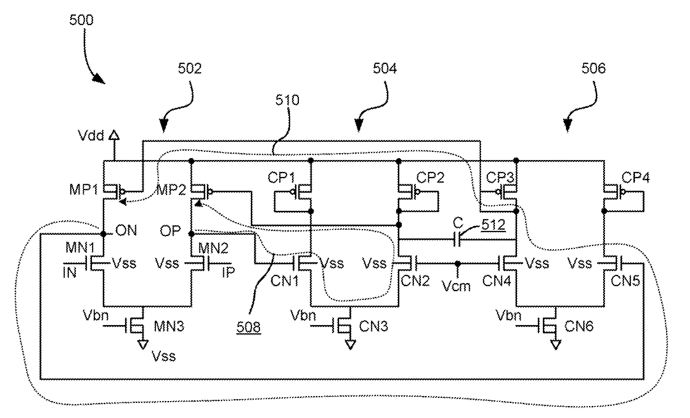
[0086]FIG. 8 illustrates an alternate embodiment 600. The inventors have found that the more the current is controlled by the common-mode feedback loop, the more efficient the feedback loop is at correcting the offset voltage. According to calculations performed by the inventors, the ratio of current controlled by the common mode feedback loop to total amount of current vs. offset voltage amplification corresponds to the following for the first stage; ratio=½, offset voltage gain=1; ratio=¼, gain=2; ratio= 1 / 7, gain=4.

embodiment 700

[0087]FIG. 9 illustrates another alternate embodiment 700, wherein the second and third sections 504. 506 have no CP1 and CP4.

embodiment 800

[0088]FIG. 10 illustrates an alternate embodiment 800, where the second and third sections 504, 506 each have an individual capacitor 802, 804 associated therewith. In this way, the first and second feedback loops 508, 510 are each coupled to an individual low-pass filter created by the respective section and capacitor combination.

[0089]While the embodiments shown in FIGS. 5 and 8-10, and variations thereof, are suitable for many applications, they may have certain limitations in other applications, making embodiments described subsequently preferred for some applications. For instance, to maintain low bandwidth filter characteristics, the current flowing through the second and third sections of the embodiments shown in FIGS. 5 and 8-10 needs to be very low. However, the first section might need a large amount of current to achieve large bandwidth for quick settling, pattern jitter reduction, and amplification purposes. In such a case, the current flowing through first section load ...


PUM


Abstract

A fully differential amplifier circuit according to one embodiment includes a first section for generating first and second output signals on first and second outputs from first and second input signals; a first feedback loop coupled to the first section, the first feedback loop including a second section for adjusting the first output signal towards a common mode voltage level, and for reducing an offset voltage of the first output signal; a second feedback loop coupled to the first section, the second feedback loop including a third section for adjusting the second output signal towards the common mode voltage level, and for reducing an offset voltage of the second output signal; and a filter section positioned on the first and second feedback loops between outputs of the second and third sections and the first section.

Description

FIELD OF THE INVENTION [0001]The present invention relates to amplifiers, and more particularly, this invention relates to fully differential amplifiers.BACKGROUND OF THE INVENTION [0002]Differential amplifiers are commonly employed in electronic devices that use analog circuits. In addition to a variety of discrete circuit applications, differential amplifiers are also used in many integrated devices such as, for example, operational amplifiers. Operational amplifiers have been the most common building blocks in analog and mixed signal circuits because of their high gain, high input impedance, high power supply noise rejection and other special characteristics. With their high gain property, one of their many applications is to amplify very small and weak signals to larger ones.[0003]The growing demand for mobile or portable electronic equipment or devices has increased the need to produce simple, lightweight, energy-efficient electronic equipment, which has resulted in an increase...

Claims


Application Information

Patent Timeline
IPC IPC(8): H03F3/45
CPCH03F3/45183H03F3/45748H03F2203/45212H03F2203/45134H03F2203/45082
Inventor YANG, TAWEIFARNSLEY, LARRY
Owner ZEST LABS INC
Why Eureka
Try Eureka