Cooling device for arrangement between two gradient coil windings of a gradient coil

a cooling device and gradient coil technology, which is applied in the direction of using reradiation, lighting and heating apparatus, instruments, etc., can solve the problems of poor heat transfer, complicated and time-consuming connection of cooling tubes with support plates, and power losses of 10 kw and more, and achieve simple production and good cooling capacity.

Active Publication Date: 2008-08-28
SIEMENS HEALTHCARE GMBH
View PDF11 Cites 14 Cited by
  • Summary
  • Abstract
  • Description
  • Claims
  • Application Information

AI Technical Summary

Benefits of technology

[0007]An object of the invention is to provide a cooling device that can be produced in a simple manner and with which a good cooling capacity can be achieved.
[0009]The invention allows the simple and cost-effective production of large-surface cooling devices. Only two larger-surface, preformed structural elements are required in the form of two plastic films made of thermoplastic material. These are locally or globally heated in a thermal reshaping procedure in order to fashion channel sections, consequently to mold channel-like recesses. The two films are provided with congruent channel section geometries so that the coolant channel sections are complementary to one another when the two films are inventively placed atop one another and are connected with one another. The films made of thermoplastic material are selected with regard to their thickness (strength) or the employed material so that the coolant channel is inherently stable, meaning that it exhibits a sufficient minimum stability and does not collapse on itself.
[0014]In an embodiment of the invention, a surface structure (for example in the form of longitudinal or transverse grooves, knobs, etc.) can be provided at least in sections in the region of the inner side of the coolant channel or channels. This surface structure serves for generation of turbulences to improve the heat transfer, as well as causing the heat transfer surface to be enlarged. This surface structuring should primarily be in regions where high power losses are to be dissipated, so the pressure loss can also be minimized.
[0016]The thickness of the employed film should be ≦0.5 mm. This ensures a sufficient inherent stability of the channel walls, and the heat transfer can be optimized since the distance between heat source (coil winding) and heat sink (coolant) is not unnecessarily increased by a film that is too thick. The films themselves should be thermally stable at least up to 120° C. to preclude any deformations or other negative effects from occurring in the casting.
[0018]A number of advantages can be achieved with the inventive cooling device. The device and the channel structure thereof are dimensionally stable; so no additional outlay for stabilization in the coil assembly and in the casting is required. Because the films can be arbitrarily deformed to shape the coolant channel sections, a very flat channel (and thus flat cooling structure) can be achieved. The channels can be made wide compared with round tubes; the cross-section of the individual cooling channel can be wide, but dimensioned flat in terms of its height. Arbitrary channel geometries can thereby be achieved. The channel geometry can also be optimally matched to the geometry of the heat sources, meaning that an optimal channel guidance is possible dependent on the winding route of the gradient coil windings. The pressure loss is less than given use of tubes since the length of the cooling channel ultimately lies only in the range of the coil length. The channel length and the coil length thus substantially correspond to one another. Furthermore, the risk of possible failure points or leaks is significantly less relative to a multi-layer glued design or a wound tube structure (in this case up to 650 m of tube are required in a gradient coil).

Problems solved by technology

Gradient currents of several hundred amperes at voltages of up to 2 kV are typical and lead to power losses of 10 kW and more, and must be dissipated in the form of heat.
The manual connection of the cooling tubes with the support plate is very complicated and time-consuming and thus expensive.
Moreover, due to the round tube cross-section only a linear contact to the heat-generating copper conductor winding (with correspondingly poor heat transfer) results.

Method used


Image

  • Cooling device for arrangement between two gradient coil windings of a gradient coil
  • Cooling device for arrangement between two gradient coil windings of a gradient coil
  • Cooling device for arrangement between two gradient coil windings of a gradient coil

Examples


Embodiment Construction

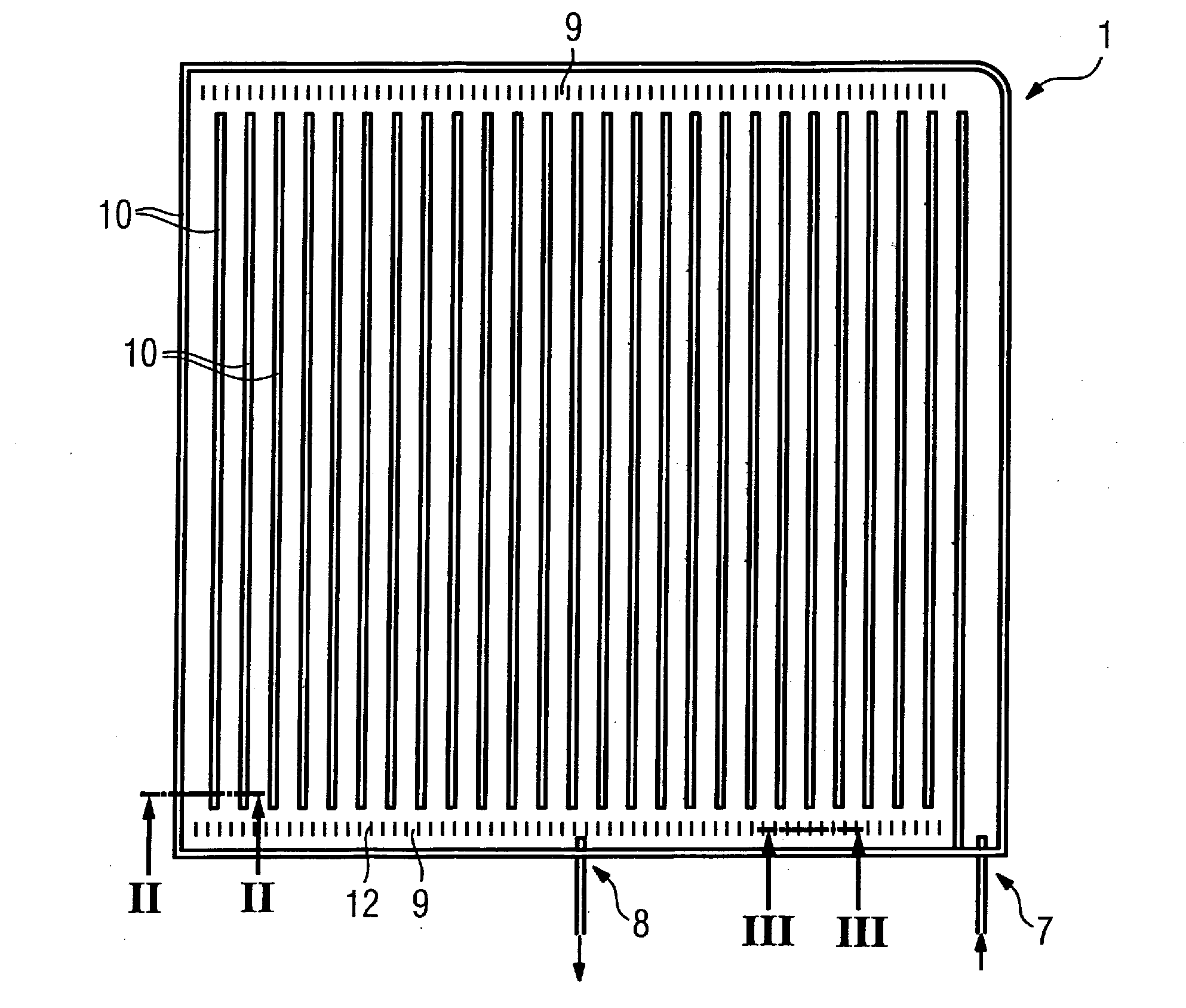
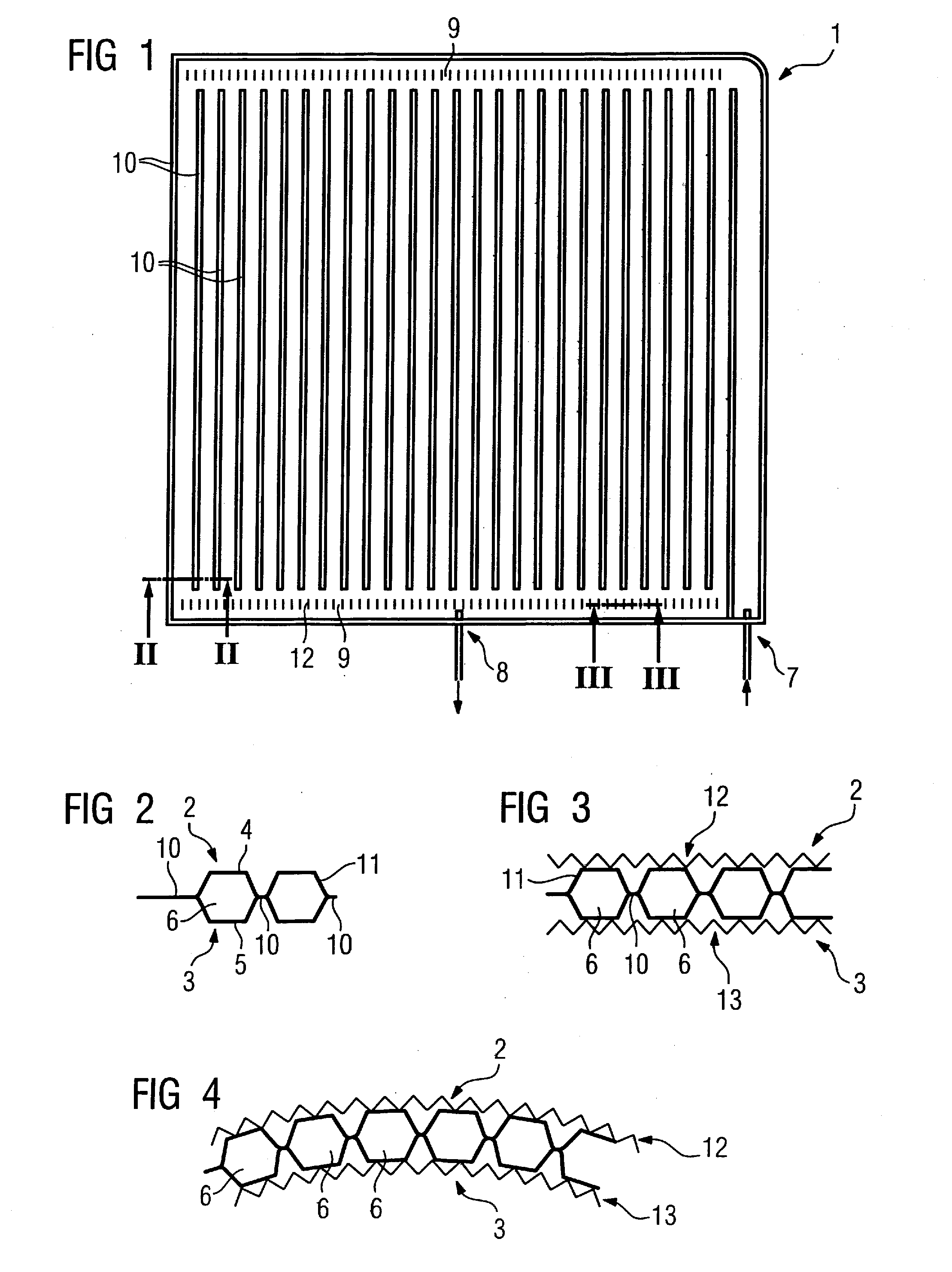
[0034]FIG. 1 shows an inventive flat cooling device 1 having (see FIG. 2) two separate films 2, 3, both comprising a thermoplastic plastic material, which films were reshaped in a reshaping method to form a specific channel geometry. Each film has been provided with coolant channel sections 4, 5 (running vertically in the shown example) in a deep drawing method, whereby the coolant channel sections 4, 5 connect to form a dimensionally-stable coolant channel 6 after the films 2, 3 are placed atop one another. This coolant channel 6 runs effectively in a meandering path from the inlet 7 to the outlet 8. Respective collection channel sections 9 (that are not shown in detail in section) are formed at the facing sides. The two films 2, 3 are connected liquid-tight with one another in the region of the connection sections 10 in a thermal connection method. This appropriately ensues directly in the reshaping tool that has two mold parts in which the films 2, 3 can respectively be placed an...


PUM

PropertyMeasurementUnit
thicknessaaaaaaaaaa
poweraaaaaaaaaa
voltagesaaaaaaaaaa

Abstract

In a cooling device for arrangement between two gradient coil windings of a gradient coil for dissipation of the heat (arising upon feeding current to the gradient coil windings) by means of a coolant flowing through one or more coolant channels in the cooling device, two films made of thermoplastic material are connected with one another, and are preformed in a thermal reshaping procedure to form coolant channel sections that are complementary to one another to form an inherently stable coolant channel after the connection.

Description

BACKGROUND OF THE INVENTION[0001]1. Field of the Invention[0002]The invention concerns a cooling device for arrangement between two gradient coil windings of a gradient coil for dissipation of the heat (arising upon current being fed to the gradient coil windings) by means of a coolant flowing through one or more coolant channels in the cooling device.[0003]2. Description of the Prior Art[0004]Gradient coils have in a known manner, a number of conductor structures cast in a resin matrix (for the most part epoxy resin) that are fed with current to generate spatially-resolved three-axis magnetic fields. Gradient currents of several hundred amperes at voltages of up to 2 kV are typical and lead to power losses of 10 kW and more, and must be dissipated in the form of heat. Cooling devices are therefore cast in the coil that are embedded between the individual coil supports in order to be able to discharge the dissipated power as effectively as possible. The thermal resistance between th...

Claims


Application Information

Patent Timeline
Patent Type & Authority Applications(United States)
IPC IPC(8): H01F27/10F28F3/12F28F21/06
CPCF28D9/0031F28F3/12Y10T29/49366G01R33/3856F28F21/065F28F2275/025
Inventor SCHUSTER, JOHANNSCHOEN, LOTHARSTOCKER, STEFAN
Owner SIEMENS HEALTHCARE GMBH
Why Eureka
Try Eureka