
Method for Controlling an Operation of a Heatable Exhaust-Gas Sensor of a Motor Vehicle

Inactive Publication Date: 2008-09-04
VOLKSWAGEN AG +1
View PDF12 Cites 18 Cited by
  • Summary
  • Abstract
  • Description
  • Claims
  • Application Information

AI Technical Summary

Benefits of technology

[0007]According to example embodiments of the present invention, a method is provided for controlling a heatable exhaust-gas sensor, in particular, in a hybrid vehicle having an automatic switchoff, the method keeping the sensor in readiness for operation for as long as possible in stop operation of the combustion engine and the subsequent restart while simultaneously protecting the sensor from damage caused by condensate action. Furthermore, a motor vehicle having a correspondingly optimized sensor control is provided.
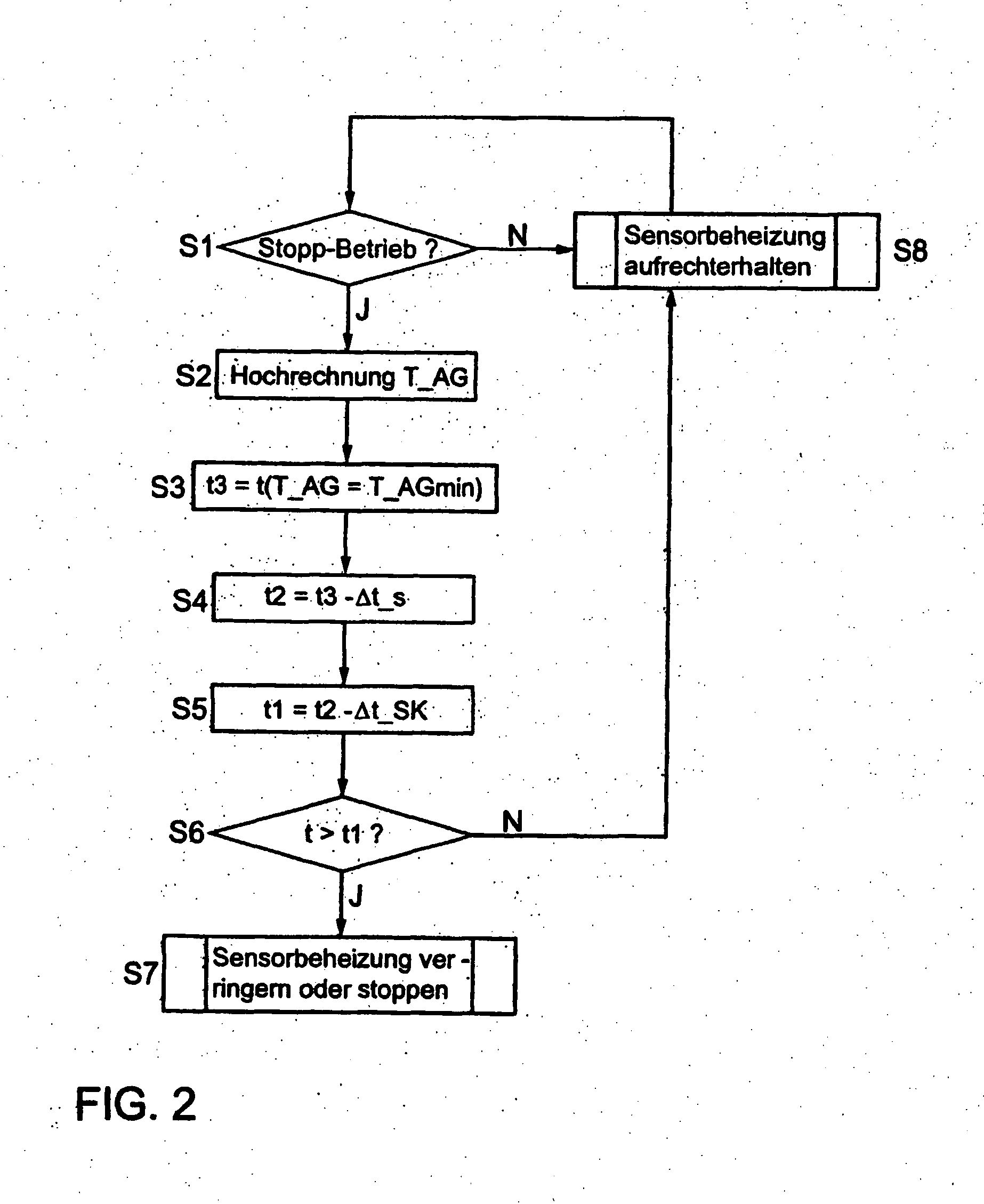
[0012]In an automatic switchoff of the combustion engine, the expected future temperature characteristic of the exhaust gas still remaining in the exhaust duct is therefore extrapolated so as to determine the instant at which it will attain or drop below the critical condensation temperature, in particular, of water. Furthermore, to prevent that the exhaust-gas sensor at this instant still has a temperature at which sensor damage by the action of condensate is to be expected, a second instant is determined at which its heating is to be reduced or interrupted completely, taking the expected cooling rate of the sensor into account. The interruption or reduction of the sensor heating is implemented only if this second instant has actually been reached. This provides that the exhaust-gas sensor is kept in readiness for operation for a maximally possible period of time when the combustion engine is switched off. If the combustion engine is switched on again before the calculated second instant has been attained, the heat output is not reduced, so that the sensor is in its operating state again immediately upon start-up of the engine, thereby allowing an optimal engine control, in particular, of the air / fuel mixture (Lambda control). The sensor heating will be reduced only when the second instant is attained, with the combustion engine shut off, thereby providing that the sensor has reached or dropped below its critical temperature when the condensation temperature of the exhaust gas is reached, so that it is protected from damage by condensate action.
[0017]After reaching the second instant, the temperature of the exhaust-gas sensor may be kept at the maximally allowed sensor temperature, and the heat output may be reduced completely or partially. This keeps the sensor in a pre-warming state and allows it to be rapidly heated to the operating temperature again in a restart of the combustion engine.

Problems solved by technology

It is conventional in this context that the ceramic elements normally used in the sensors exhibit a very sensitive response to the entry of condensate, especially liquid water, which may lead to damage and malfunction of the sensor.
The control of the sensor operation, in particular the sensor heating, is problematic in hybrid vehicles.
If, in stop operation of the combustion engine, the exhaust gas still remaining in the exhaust system cools to below the condensation temperature and the sensor is kept at its operating temperature in the meantime, then condensation precipitation may occur and the sensor may be acted upon by the condensate, especially liquid water, in a subsequent restart of the engine, so that damage to the sensor may result.
On the other hand, if the sensor heating is also reduced or deactivated as soon as the combustion engine is automatically switched off, then the delay at which the sensor regains its operating temperature after a restart of the engine leads to an insufficiently precise engine control and thus to increased emission levels and / or increased fuel consumption.

Method used


Image

  • Method for Controlling an Operation of a Heatable Exhaust-Gas Sensor of a Motor Vehicle
  • Method for Controlling an Operation of a Heatable Exhaust-Gas Sensor of a Motor Vehicle
  • Method for Controlling an Operation of a Heatable Exhaust-Gas Sensor of a Motor Vehicle

Examples


Embodiment Construction

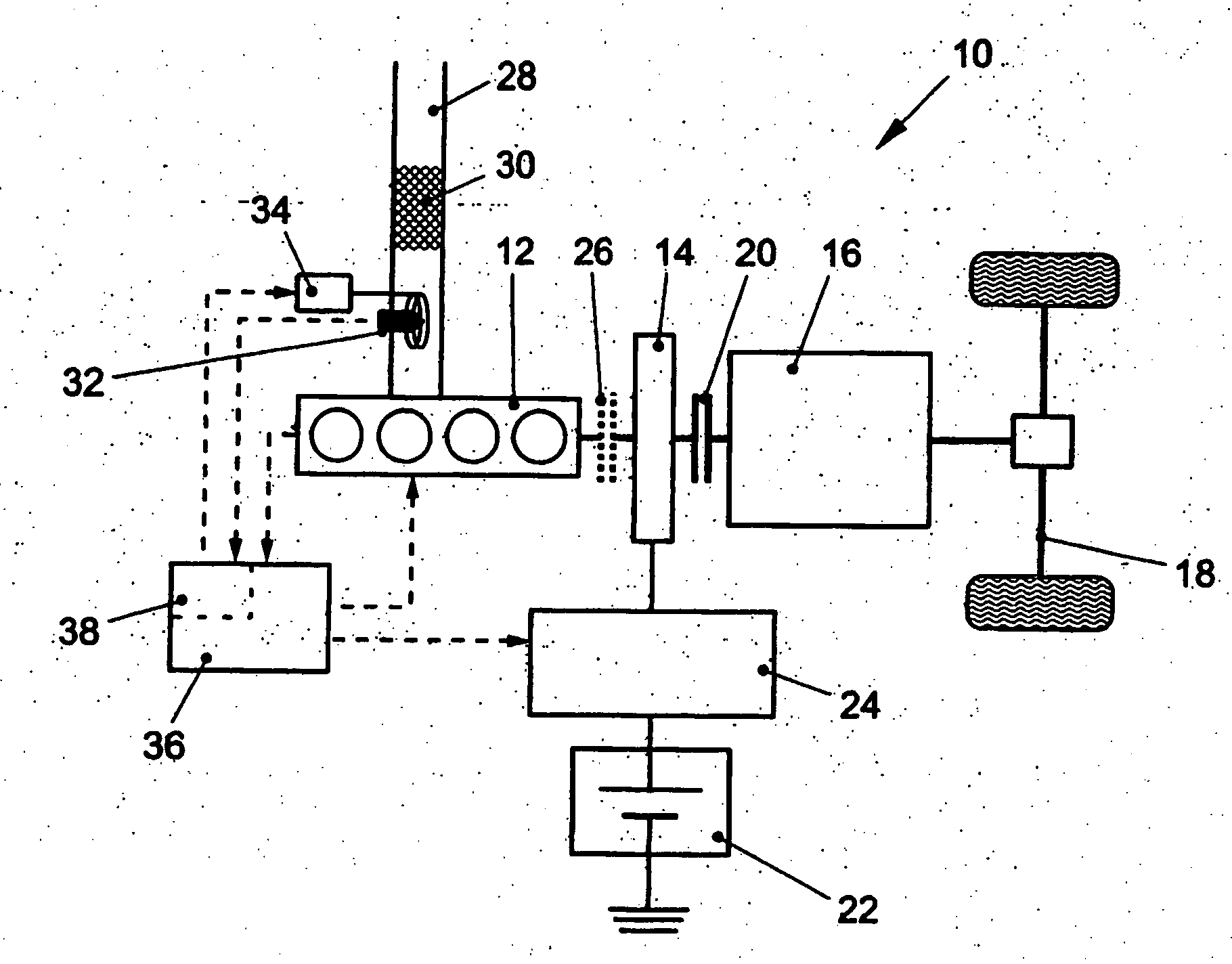
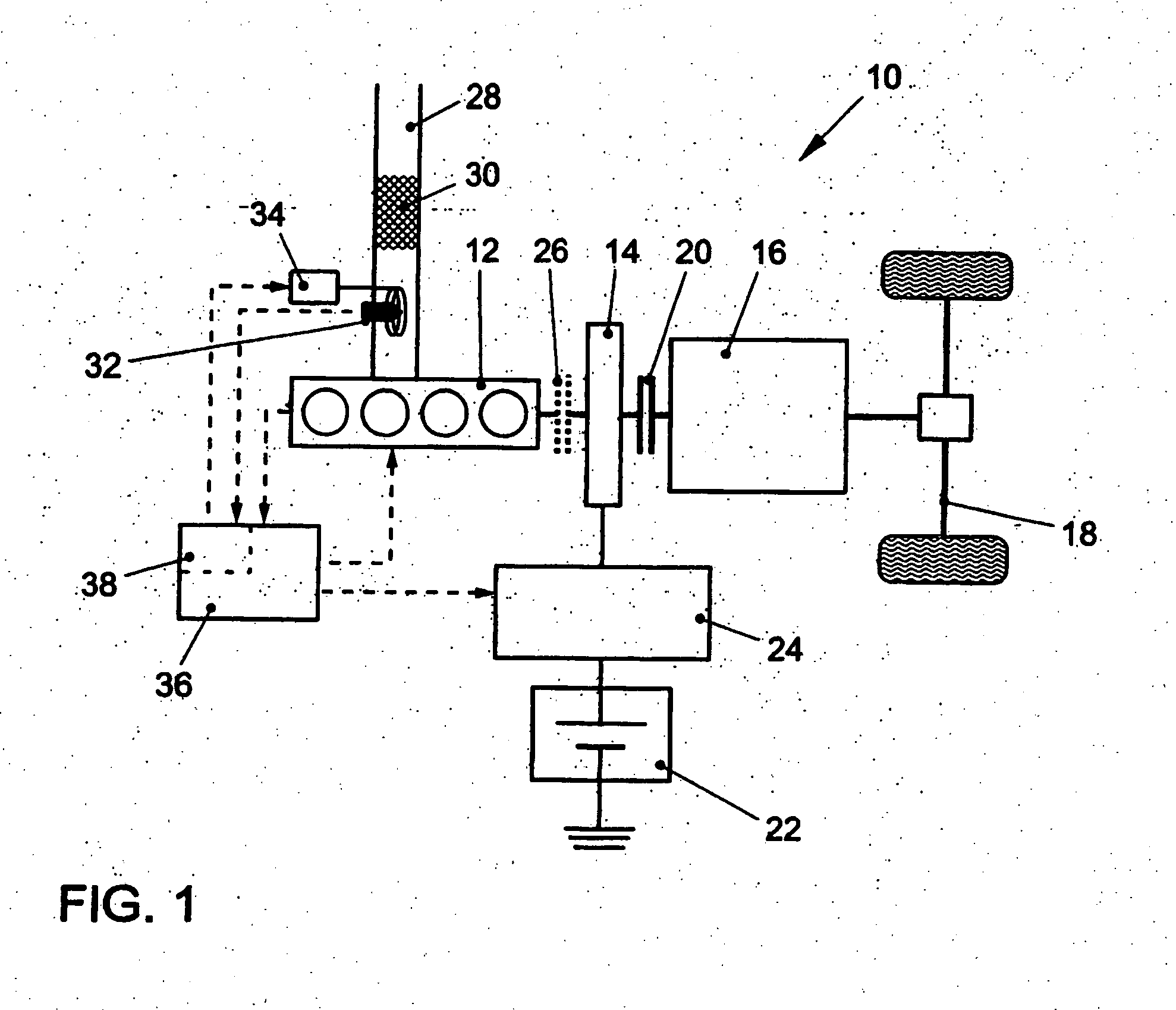
[0023]In FIG. 1, 10 as a whole denotes a hybrid drive unit of a hybrid vehicle. The driving of the vehicle is optionally or simultaneously implemented by a conventional combustion engine 12 (Otto or diesel engine) and an electromotor 14, which both act on the same shaft. In particular, electromotor 14 acts on the crankshaft of combustion engine 12 either directly or via a transmission or via a belt, a toothed belt or some other non-positive and / or positive connection. Via a transmission 16 (automatic or manual transmission), combustion engine 12 and electromotor 14 are connected to a drive train 18. The decoupling of the drive shafts of combustion engine 12 or electromotor 14 from transmission 16 is implemented with the aid of a clutch 20, which is able to be released by the driver by activation of a clutch pedal and which is locked when not activated.

[0024]Electromotor 14, which is a three-phase asynchronous motor or three-phase synchronous motor, for instance, may optionally be op...


PUM


Abstract

A method is for controlling the operation of an exhaust-gas sensor disposed in an exhaust duct of a motor vehicle and equipped with an internal or external sensor heating device, the motor vehicle including a combustion engine and an automatic switchoff, which causes an automatic switching off of the combustion engine when at least one stop condition is present. It is provided that: (a) following an automatic switching off of the combustion engine by the automatic switchoff, a first future instant is determined at which the exhaust-gas temperature in the exhaust duct will drop below a condensation temperature below which condensate precipitation from the exhaust gas may occur; (b) a second instant is determined at which a heat output of the sensor heating device must be interrupted or reduced so that a sensor temperature of the exhaust-gas sensor will have dropped to a maximally allowed sensor temperature no later than the first future instant; and the heat output of the sensor heating device is interrupted or reduced when the second instant is attained.

Description

FIELD OF THE INVENTION[0001]The present invention relates to a method for controlling the operation of an exhaust-gas sensor disposed in an exhaust duct of a motor vehicle and having an internal or external sensor heating device, the motor vehicle having an internal combustion engine and an automatic switchoff, which causes an automatic switching off of the combustion engine or which suppresses its renewed switching on when at least one stop condition is present. The motor vehicle is, in particular, a hybrid vehicle, which has at least one additional electromotor for its driving. Furthermore, the present invention relates to a motor vehicle having a corresponding sensor control.BACKGROUND INFORMATION[0002]Motor vehicles usually have one or several exhaust-gas sensors disposed in the exhaust duct, which emit a measuring signal that is proportional to a concentration of at least one exhaust-gas component and allows its concentration to be determined. For instance, Lambda sensors suppl...

Claims


Application Information

Patent Timeline
IPC IPC(8): F01N11/00B60K6/48
CPCB60K6/48Y02T10/47B60W10/06B60W2510/068F01N9/005F01N11/00F01N2560/025F01N2560/026F01N2560/20F02D41/042F02D41/1446F02D41/1447F02D41/1494F02N11/0814Y02T10/6221B60L2240/445Y02T10/40Y02T10/62
Inventor ZILLMER, MICHAELHOLZ, MATTHIASPOTT, EKKEHARDPROCHAZKA, DAVID
Owner VOLKSWAGEN AG
Learn More