
Connecting structure for an aircraft or spacecraft and method for producing the same

Active Publication Date: 2008-09-04
AIRBUS OPERATIONS GMBH
View PDF6 Cites 15 Cited by
  • Summary
  • Abstract
  • Description
  • Claims
  • Application Information

AI Technical Summary

Benefits of technology

[0007]An object of the present invention is to provide an improved connecting structure between a structural component and a stringer, it being intended in particular to prevent detachment of the stringer from the structural component under the effect of impact.

Problems solved by technology

In addition, the fuselage shell is occasionally exposed to impact, that is to say brief, intensive force effects.
Such instances of impact in such fuselage shells of fiber composite material are often the initial cause of damage in the fuselage shell.
The consequence is then a brittle fracture of the resin matrix in these connecting regions.
Then the T stringer becomes detached from the fuselage shell and a catastrophic collapse of the latter occurs.

Method used


Image

  • Connecting structure for an aircraft or spacecraft and method for producing the same
  • Connecting structure for an aircraft or spacecraft and method for producing the same
  • Connecting structure for an aircraft or spacecraft and method for producing the same

Examples


Embodiment Construction

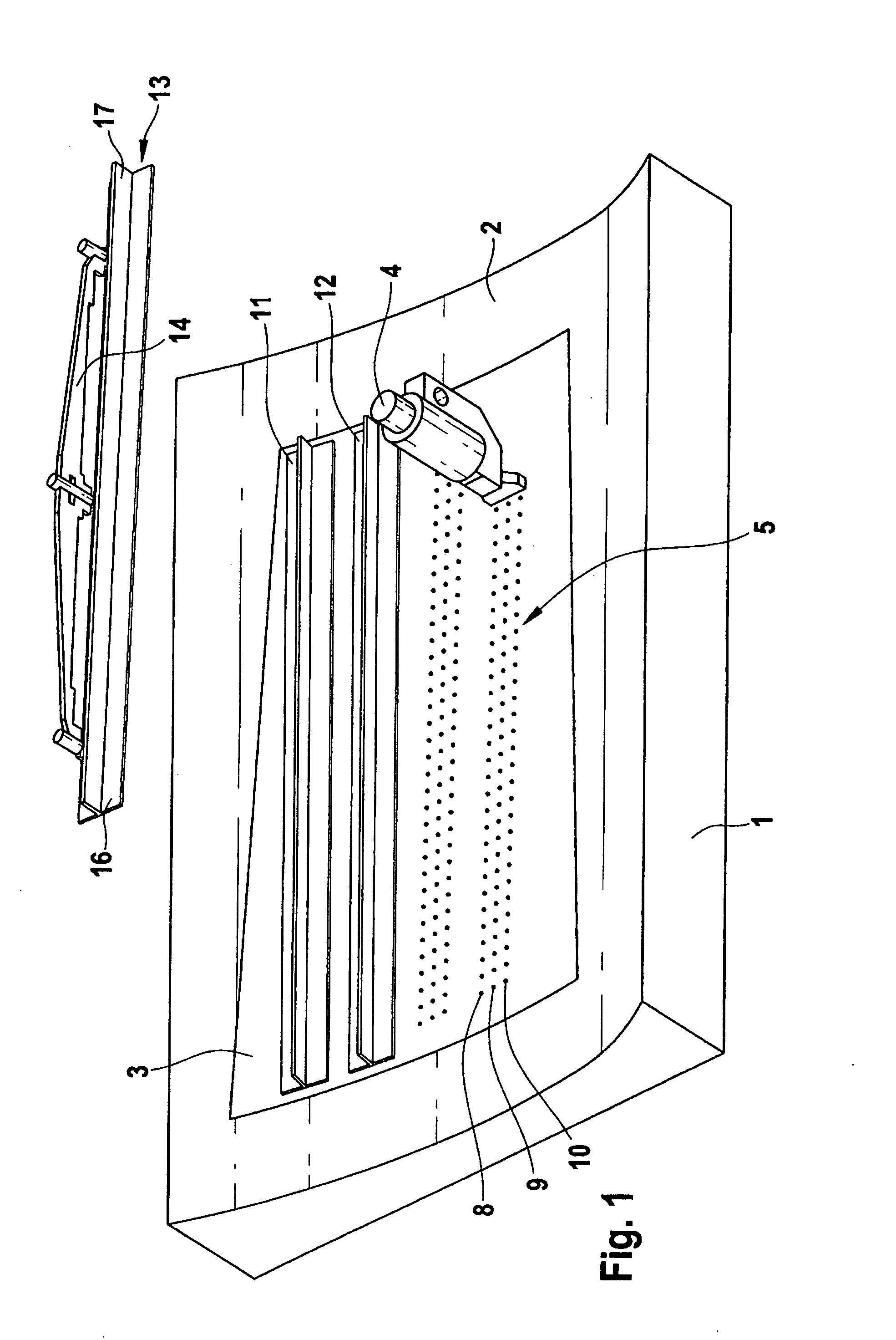
[0045]FIG. 1 shows a laminating device 1, which has a contour 2. The contour 2 is of such a form that it shapes a skin shell 3, for example a fuselage shell of an aircraft, the skin shell for example being constructed from not yet cured layers of CRP material.

[0046]An application device 4 applies a thermoplastic material 5 to the skin shell 3. In this exemplary embodiment, the thermoplastic material 5 may have, in terms of percentages by weight, a composition of 40% polyethylene and 60% epoxy resin.

[0047]The application of the thermoplastic material 5 is thereby performed along a number of parallel connecting regions, preferably three parallel connecting regions 8, 9 and 10. The thermoplastic material 5 is applied here as powder. Equally, however, laid fiber fabrics of thermoplastic material could also be placed on and / or arranged such that they overlap with the fibers of the skin shell. Subsequently, T stringers 11, 12 and 13 are laid by means of a laying device 14 onto the connect...


PUM

PropertyMeasurementUnit
Fractionaaaaaaaaaa
Fractionaaaaaaaaaa
Fractionaaaaaaaaaa

Abstract

The present invention relates to a connecting structure for an aircraft or spacecraft, with a structural component and a stringer. The stringer is connected to the structural component by means of connecting regions. In order to reduce stress peaks that result for example from impact in the structural component, a high impact material is introduced into at least one of the connecting regions to provide a local increase in the energy absorbing capacity of the at least one connecting region.

Description

CROSS-REFERENCE TO RELATED APPLICATIONS[0001]This application claims the benefit of U.S. Provisional Application No. 60 / 851,497, filed Oct. 13, 2006, the entire disclosure of which is herein incorporated by reference.FIELD OF THE INVENTION[0002]The present invention relates to a connecting structure for an aircraft or spacecraft and to a method for producing such a connecting structure for an aircraft or spacecraft.BACKGROUND OF THE INVENTION[0003]Although it can be applied to any desired connecting structures, the present invention and the problems on which it is based are explained in more detail with reference to a fuselage shell of an aircraft stiffened by means of stringers.[0004]Fuselage shells and stringers are increasingly being produced from fiber composite materials, in particular from carbon fiber reinforced plastic (CRP). Fuselage shells and stringers have in this case a construction comprising a number of layers of laid fiber fabric which are joined to one another by me...

Claims


Application Information

Patent Timeline
IPC IPC(8): B64C1/06
CPCB29C70/24B29C70/543Y02T50/433B64F5/0009B64C1/12B29L2031/3076B29K2995/0089B29L2031/3082B29L2031/3085B29C65/4815B29C65/486B29C66/05B29C66/1122B29C66/532B29C66/61B29C66/7212B29C66/73751B29C66/73753B29C66/81422B29C65/02B64F5/10B29C66/21Y02T50/40B29K2307/04
Inventor EBERTH, ULRICH
Owner AIRBUS OPERATIONS GMBH
Learn More