Flat fuel cell assembly and fabrication thereof
- Summary
- Abstract
- Description
- Claims
- Application Information
AI Technical Summary
Benefits of technology
Problems solved by technology
Method used
Image
Examples
first embodiment
[0056] First Embodiment
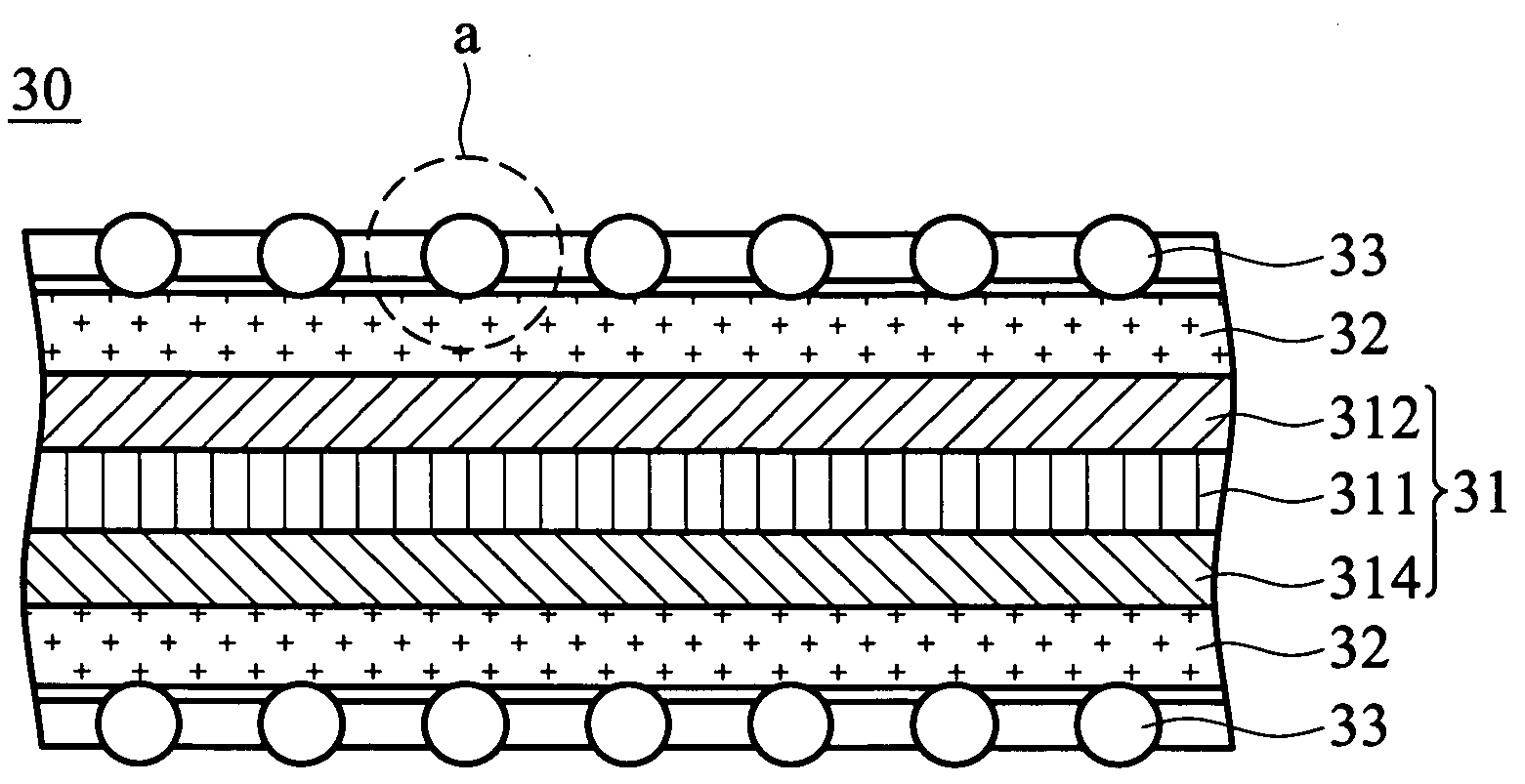
[0057]FIG. 4A is a cross section of the flat fuel cell assembly in a first embodiment. To simplify the drawing, the fuel cell assembly shows only, but is not limited to, two fuel cells.
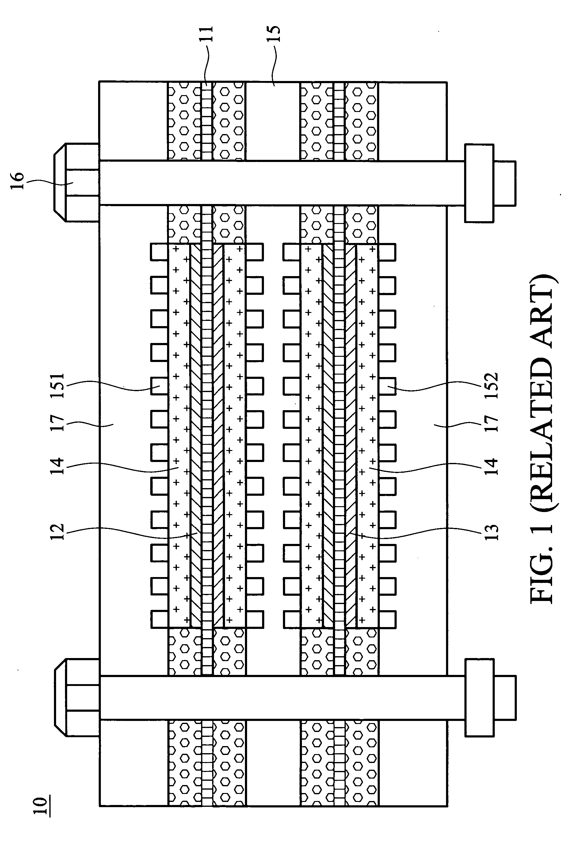
[0058] In FIG. 4A, the fuel cell assembly 40 has two fuel cells 30a, 30b, an insulation frame 42, and two flow-guiding plates 43a, 43b. A metal net 41 is first bonded to the anode of the fuel cell 30a and the cathode of the fuel cell 30b by the b-stage adhesive, forming a connecting electrodes therebetween. The flexing portion 411 of the connecting metal nets 41 is embedded in the center portion of the insulation frame 42, which can protect the flexing portion 411 from damage. Furthermore, the insulation frames 42 comprise a ceramic plate, or are formed of PC, PE, fiber-enhanced resin, or other polymer by injection molding.
[0059] Furthermore, the connecting metal nets of the fuel cell assembly 40 can be two metal nets combined within the connecting portion as shown in FIG. 4B....
second embodiment
[0064] Second Embodiment
[0065]FIG. 5A is an exploded perspective view of the flat fuel cell assembly in the second embodiment, and FIG. 5B a cross section thereof. To simplify the drawings, the flat fuel cell assembly 50 is shown with, but is not limited to, four fuel cells 30a˜30d.
[0066] In FIG. 5A, the flat fuel cell assembly 50 includes an insulation frame and a plurality of fuel cells 30a˜30d connected in series. The insulation frame includes an enclosure 51 and two covers 52a, 52b. The enclosure 51 is a rectangular insulation frame to support the covers 52a, 52b, and a connecting electrodes 511 is embedded in a sidewall thereof. The covers 52a, 52b both have two rectangular openings 521. The fuel cells 30a˜30d are disposed on the covers 52a, 52b, covering the openings 521. Moreover, the covers 52a, 52b can be prepared according the structure of the flat fuel cells as shown in FIGS. 4B˜4D and combined with the enclosure 51. The enclosure 51 and the covers 52a, 52b of the insula...
third embodiment
[0071] Third Embodiment
[0072] During fabrication of dual-cell modules of the second embodiment shown in FIG. 5A, the metal nets 54a, 54b are difficult to flex and bond to two fuel cells at the same time. Accordingly, the present invention provides another easily fabricated structure for the flat fuel cell assembly.
[0073]FIG. 6 is a cross section of the flat fuel cell assembly in the third embodiment of the invention. To simplify the drawings, the flat fuel cell assembly 60 is shown with, but is not limited to, six fuel cells 30a˜30f. In FIG. 6, the flat fuel cell assembly 60 includes an insulation frame and a plurality of fuel cells 30a˜30f connected in series. The insulation frame has an enclosure 61 and two covers 62a, 62b. The enclosure 61, similar to the second embodiment, is a rectangular insulation frame to support the covers 62a, 62b, and a connecting electrodes 61c is embedded in a sidewall thereof. The covers 62a, 62b both have three rectangular openings. The fuel cells 30...
PUM
| Property | Measurement | Unit |
|---|---|---|
| Temperature | aaaaa | aaaaa |
| Temperature | aaaaa | aaaaa |
| Temperature | aaaaa | aaaaa |
Abstract
Description
Claims
Application Information
 - R&D
- Intellectual Property
- Life Sciences
- Materials
- Tech Scout
- Unparalleled Data Quality
- Higher Quality Content
- 60% Fewer Hallucinations
Browse by: Latest US Patents, China's latest patents, Technical Efficacy Thesaurus, Application Domain, Technology Topic, Popular Technical Reports.
© 2025 PatSnap. All rights reserved.Legal|Privacy policy|Modern Slavery Act Transparency Statement|Sitemap|About US| Contact US: help@patsnap.com


