Power supply system for driving electric rotating machine

Active Publication Date: 2008-09-04
FUJI ELECTRIC CO LTD
View PDF6 Cites 14 Cited by
  • Summary
  • Abstract
  • Description
  • Claims
  • Application Information

AI Technical Summary

Benefits of technology

[0018]According to the invention, there can be achieved an advantage which enables the simultaneous realization of reduction in electrical loss when using a matrix converter and reduction in a system loss and enhancement of a motor output by raised voltage.
[0019]Namely, according to the first aspect of the invention, only one time power conversion is enough, which enables the whole system to have a high efficiency. Moreover, according to the second aspect of the invention, it becomes possible to apply a high voltage to the second electric rotating machine, which allows the transformer to be downs

Problems solved by technology

This causes a problem of increasing losses produced in the inverters.
Therefore, when a slight potential difference is caused between the output of the matrix converter MC and the output of the inverter INV2, the output current of the matrix converter MC and the output current of the inverter INV2 becomes

Method used


Image

  • Power supply system for driving electric rotating machine
  • Power supply system for driving electric rotating machine
  • Power supply system for driving electric rotating machine

Examples


Example

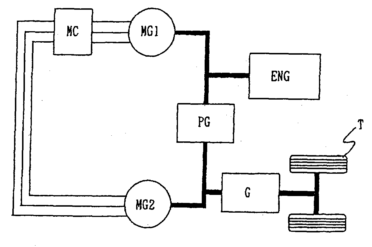
[0032]FIG. 1 is a schematic view showing an arrangement of an embodiment of a power supply system for driving an electric rotating machine according to the invention provided in a driving system of a hybrid vehicle.

[0033]In a hybrid vehicle, a part of the energy generated by the rotation of an engine ENG is directly used for driving wheels T via a power split mechanism PG. The rest of the generated energy is used for rotating a generator MG1 to generate electric power. The alternating-current electric power generated by the generator MG1 is converted to a desired alternating-current electric power by an alternating-current to alternating-current direct converter MC to drive a motor MG2. For example, the alternating-current to alternating-current direct converter MC receives an instruction from a control circuit not shown to convert the frequency of the inputted alternating-current electric power, outputting the electric power with the converted frequency for driving the motor MG2. I...


PUM


Abstract

An electric power supply system for driving an electric rotating machine has a generator supplied with driving power from an engine to generate alternating-current electric power and a matrix converter as an alternating-current to alternating-current direct converter supplied with the alternating-current electric power to output arbitrary alternating-current electric power. By driving a motor with the alternating-current electric power supplied from the matrix converter, only one time electric power conversion is carried out to provide high efficiency in the whole system. In addition, electric power loss can be reduced so as to enhance a motor output when the system is applied to a vehicle power supply system.

Description

CROSS-REFERENCE TO RELATED APPLICATION[0001]This application claims priority from Japanese Patent Application 2007-035942 filed on Feb. 16, 2007 the content of which is incorporated herein by reference.BACKGROUND[0002]The present invention relates to a power supply system for driving an electric rotating machine, particularly to a power supply system for driving an electric rotating machine suited for vehicle use.[0003]FIG. 10 is a schematic view showing a first example of the arrangement of a related power supply system for driving an electric rotating machine provided in a driving system of a hybrid vehicle. The power supply system is disclosed in the following non-patent document: H. Hanada et al., TOYOTA Technical Review Vol. 54, No. 1, August 2005, pp. 42-51.[0004]The first example is presented as a power supply system in a driving system of a hybrid vehicle provided with both of an internal combustion engine and a motor as driving power sources of a vehicle. The driving system...

Claims


Application Information

Patent Timeline
IPC IPC(8): H02P4/00H02P25/30B60L50/16
CPCB60L11/123B60L2210/20Y02T10/725Y02T10/7077Y02T10/6217B60L50/61Y02T10/62Y02T10/70Y02T10/72Y02T10/7072
Inventor TAMAI, YASUHIROODAKA, AKIHIROGEKINOZU, MASAKAZU
Owner FUJI ELECTRIC CO LTD
Why Eureka
Try Eureka