Internal combustion engine system and control method for internal combustion engine

Active Publication Date: 2018-07-19
TOYOTA JIDOSHA KK
View PDF0 Cites 5 Cited by
  • Summary
  • Abstract
  • Description
  • Claims
  • Application Information

AI Technical Summary

Benefits of technology

The invention relates to improving the knocking limit and the output of a supercharged engine. An external EGR gas can be introduced into the cylinder to increase the amount of air charged to the engine and improve knocking limit without needing to close the intake valve early. The use of the high-speed cam at the low-speed side of the high-load region further enhances the output of the engine.

Problems solved by technology

In addition, supercharging effects of the supercharger can also increase the amount of air charged into a cylinder.
Accordingly, a problem arises when the operating state of the engine shifts from the middle-load region to the high-load region.
Specifically, the problem is a lowered knocking limit due to reduction in the target EGR rate when the operating state of the engine shifts from the middle-load region to the high-load region.
When the driving cam is switched while the actual EGR rate is changing, combustion becomes unstable and torque fluctuation increases.
Accordingly, when the second cam is selected as the driving cam, turbulence in the cylinder becomes smaller than the turbulence generated when the first cam is selected as the driving cam, which leads to decrease in combustion speed.
When the driving cam is switched while the fuel injection timing of the injector is changing, combustion becomes unstable, and torque fluctuation increases.

Method used


Image

  • Internal combustion engine system and control method for internal combustion engine
  • Internal combustion engine system and control method for internal combustion engine
  • Internal combustion engine system and control method for internal combustion engine

Examples


first embodiment

[0044]First, the present disclosure will be described with reference to FIGS. 1 through 10.

[0045]FIG. 1 is a schematic view illustrating a configuration example of a system according to the first embodiment of the present disclosure. The system illustrated in FIG. 1 is a system for an internal combustion engine mounted on a vehicle. The system illustrated in FIG. 1 includes an internal combustion engine 10 as a driving source. The internal combustion engine 10 is a four-stroke cycle reciprocating engine, and is also an inline three-cylinder engine. The number of cylinders and cylinder arrangement of the internal combustion engine 10 are not particularly limited. The internal combustion engine 10 has a relatively high geometric compression ratio of 11 or more. Each cylinder of the internal combustion engine 10 communicates with an intake pipe 12 and an exhaust pipe 14.

[0046]A description is first given of an intake system of the internal combustion engine 10. In the vicinity of an in...

second embodiment

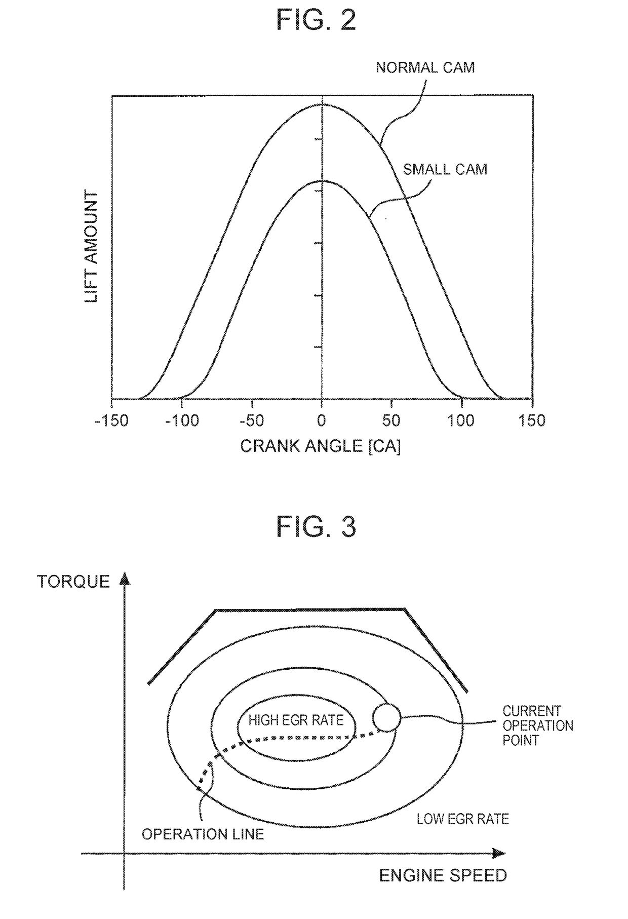
[0081]To cope with this situation, in the second embodiment, the small cam (small valve duration) is selected in the high-torque and low-speed region, so that the state where the actual compression ratio is high can be eliminated. As already described, the small cam (small valve duration) is smaller in valve duration that the small cam (large valve duration). Accordingly, when the small cam (small valve duration) is used as the driving cam, the intake valve can be closed earlier than the case of using the small cam (large valve duration) as the driving cam, so that the actual compression ratio and the suction efficiency can considerably be lowered. Therefore, the decrease in the knocking limit can be suppressed. In the high-torque and low-speed region, the back pressure is less than the stipulated value. Accordingly, the WGV is hardly opened before and after the switching to the small cam (small valve duration). That is, in the high-torque and low-speed region, the suction efficienc...

third embodiment

[0086]The system of the third embodiment is a hybrid system including an internal combustion engine and in addition, a motor-generator (MG) as a driving source of the vehicle. The hybrid system includes publicly known configuration including a driving shaft, a power split device, a power control unit (PCU), and a battery, other than the MG. Since the configuration of the hybrid system is publicly known, and there are no limitations on the configuration in the present invention, further description about the hybrid system is omitted.

[0087]FIGS. 14 through 15 are explanatory views illustrating a cooling system in the system according to the third embodiment of the present invention. The system of the third embodiment includes two cooling systems. The cooling system illustrated in FIG. 14 circulates a relatively high-temperature coolant among the internal combustion engine 10, the EGR cooler 40, and a radiator 78. In the cooling system, the coolant flowing into a water pump 80 from the...


PUM


Abstract

An electronic control unit is configured to select a first cam as a driving cam of an intake valve in a first operation range where a target value of an EGR rate is set to a specified EGR rate, and is configured to select a second cam as the driving cam in a second operation range smaller in valve duration and lift amount than the first cam. Accordingly, in most of the operation regions, the first cam is selected, and the second cam is selected only in a high-torque and high-speed region. When the second cam is selected in the high-torque and high-speed region, the state where an actual compression ratio is high can be eliminated, and suction efficiency can be decreased. Therefore, decrease in a knocking limit can be suppressed.

Description

INCORPORATION BY REFERENCE[0001]The disclosure of Japanese Patent Application No. 2017-006115 filed on Jan. 17, 2017 including the specification, drawings and abstract is incorporated herein by reference in its entirety.BACKGROUND1. Technical Field[0002]The present disclosure relates to internal combustion engine systems and control methods for internal combustion engines, and relates more specifically to an internal combustion engine system and a control method for an internal combustion engine that control engine output by changing operational characteristics of an intake valve.2. Description of Related Art[0003]Disclosed in Japanese Patent Application Publication No. 6-108860 is a controller of an internal combustion engine, the controller being configured to change a closing time of an intake valve by switching two types of intake cams in accordance with an operating state of an engine with a supercharger. In this conventional controller, a low-speed intake cam is selected at a ...

Claims


Application Information

Patent Timeline
IPC IPC(8): F02D41/00F02D41/40F02B37/18F01L1/047F02M26/06F02P5/04F02M31/20
CPCF02D41/0007F02D41/0052F02D41/401F02B37/18F01L1/047F02M26/06F02P5/045F02M31/20F02D2041/001F02D41/0072F02D2200/021F02D19/024F02D19/061F02D23/00F02B29/04F02D13/0234F02D37/02F02D41/0002F02D41/005F02D41/30F02D2200/1002F02D2200/101F02D41/38F02D43/04F01L13/0036F02D23/005F02D37/00Y02T10/12Y02T10/40F02D41/345F02P5/1502F02M26/48F02D13/0261F02D41/006
Inventor HOTTA, SHINTAROKATO, AKIRAMITANI, SHINICHI
Owner TOYOTA JIDOSHA KK
Why Eureka
Try Eureka