Optical Pick-Up and/or Recording Device

Inactive Publication Date: 2008-09-04
KONINKLIJKE PHILIPS ELECTRONICS NV
View PDF11 Cites 7 Cited by
  • Summary
  • Abstract
  • Description
  • Claims
  • Application Information

AI Technical Summary

Benefits of technology

[0004]It is an object of the invention to provide an optical pick-up and/or recording device for a near field optical

Problems solved by technology

The near field system known has the disadvantage that an alignment of the lens with respect to the surfa

Method used


Image

  • Optical Pick-Up and/or Recording Device
  • Optical Pick-Up and/or Recording Device
  • Optical Pick-Up and/or Recording Device

Examples


Embodiment Construction

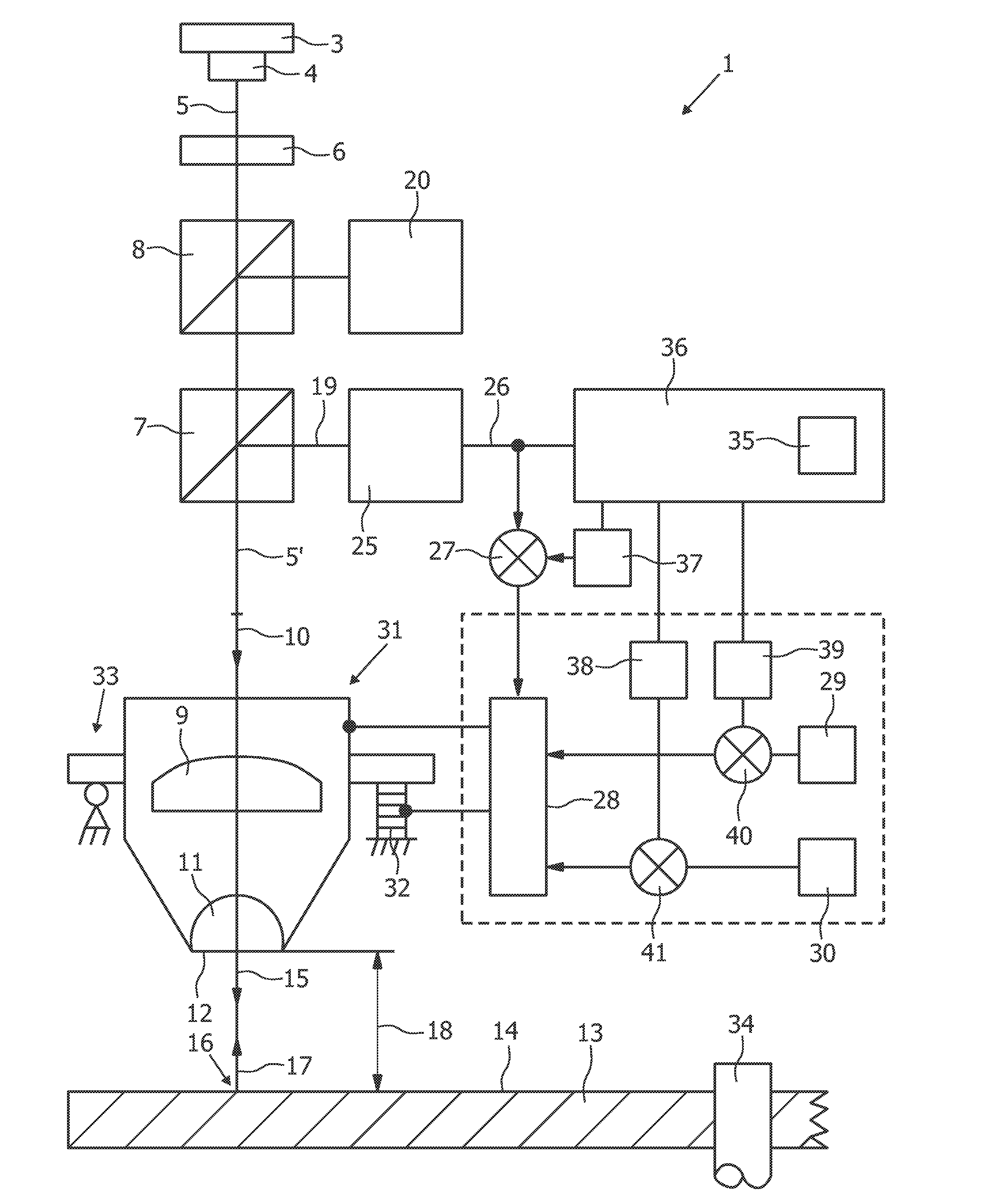
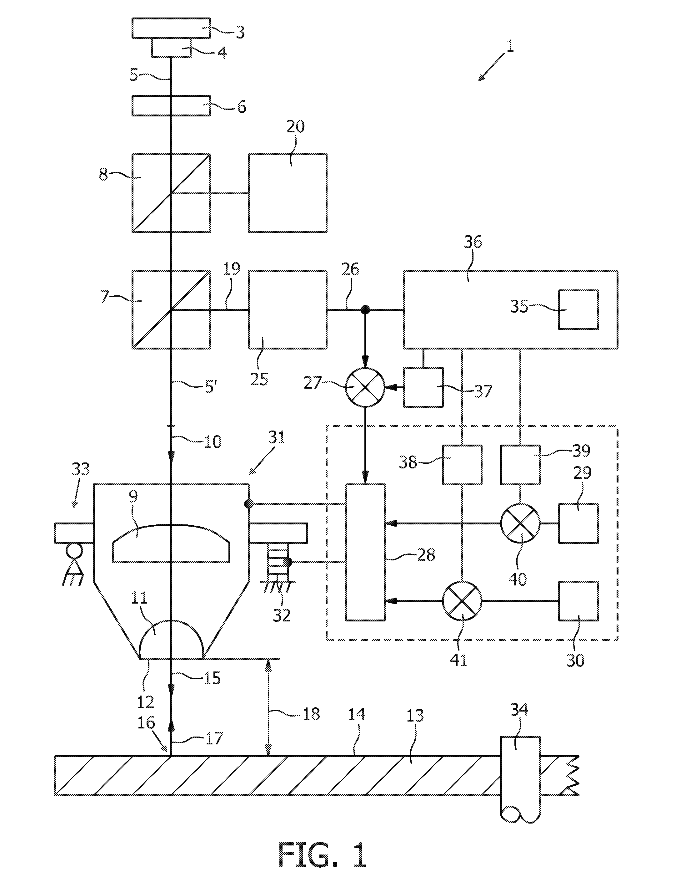
[0019]FIG. 1 shows an optical pick-up and / or recording device 1 according to a first embodiment of the invention. The optical pick-up and / or recording device 1 according to the first embodiment of the invention comprises an optical head. It may be possible that some elements of the optical pick-up and / or recording device 1 as claimed are not located on the optical head, but somewhere else in the optical storage system, for example at a main board.

[0020]The optical pick-up and / or recording device 1 can be used in an optical storage system, especially for two-dimensional optical data storage and three-dimensional holographic storage. The optical storage system can use a two-dimensional optical data storage disk, a storage medium for holographic storage or another optical storage medium. But, the optical head and the optical pick-up and / or recording device 1 are not limited to this mentioned data storage systems and can also be used in other applications.

[0021]The optical pick-up and / o...


PUM


Abstract

For optical data storage applications a near field optical system can be used. In near field optical systems an accurate control of the distance between the solid immersion lens and the disc surface is crucial. After the correction of a tilt between the lens and the disc, the laser beam may not always be parallel to the optical axis. This has a detrimental effect on the gap signal used for the distance control. The optical head of the invention comprises a gap signal correcting unit to take care of such detrimental effects.

Description

FIELD OF THE INVENTION[0001]The present invention relates to an optical head for a near field optical storage system and to an optical pick-up and / or recording device. More particularly, the present invention relates to an optical head and an optical pick-up and / or recording device for two-dimensional optical data storage.BACKGROUND OF THE INVENTION[0002]State of the art document Optical Data Storage 2004, F. Zijp et al., Proceedings of SPIE Vol. 5380, pp. 209 to 223, describes a near field system. Thereby, a near field read-out of a 50 GB first-surface disc with a very high numerical aperture of 1.9 is proposed. The known near field system comprises a moving mechanism adapted to vary a distance between a front surface of a solid immersion lens and a surface of an optical disc. Thereby, for read-out operations the solid immersion lens is positioned at a constant distance that lies within the evanescent decay distance of a part of the focused electromagnetic field, typically less tha...

Claims


Application Information

Patent Timeline
IPC IPC(8): G11B7/00G11B7/135
CPCG11B7/0908G11B7/1387G11B7/0956G11B7/09G11B7/085
Inventor ZIJP, FERRYVERSCHUREN, COEN ADRIANUS
Owner KONINKLIJKE PHILIPS ELECTRONICS NV
Why Eureka
Try Eureka