Nested modulator

Active Publication Date: 2008-09-04
SUMITOMO OSAKA CEMENT CO LTD +1
View PDF2 Cites 31 Cited by
  • Summary
  • Abstract
  • Description
  • Claims
  • Application Information

AI Technical Summary

Benefits of technology

[0015]In accordance with the invention according to the first aspect of the present invention, a polarization reversal region is formed in a portion of a sub-branching waveguide of each of the sub-Mach-Zehnder waveguides, the modulating electrode is formed of signal electrodes including introduced signal electrodes, branching single electrodes and lead signal electrodes as well as ground electrodes for each of sub-Mach-Zehnder waveguides, and the branching signal electrodes which branch from the introduced signal electrode are placed so as to work on two sub-branching waveguides for each of the sub-Mach-Zehnder waveguides, and therefore, a single signal electrode is introduced into each of the sub-MZ waveguides, thus making the wiring of the electrodes simple. In addition, in each of the sub-MZ waveguides, an efficient modulation operation can be implemented using polarization reversal of the substrate and the branching signal electrode, and the drive voltage can be lowered in the same manner as in the case where a signal electrode is provided for each sub-branching waveguide.
[0016]In accordance with the invention according to the second

Problems solved by technology

In the case of FIG. 2, only a single signal electrode is formed for each sub-MZ waveguide, and therefore, the waveguides and the signal electrodes are at a distance from each other, and thus, there is a disadvantage in that the drive voltage becomes high though there is an advantage in that the structure becomes relatively simple.
However, it is necessary to always secure two signal electrodes for each of the sub

Method used


Image

  • Nested modulator
  • Nested modulator
  • Nested modulator

Examples


Embodiment Construction

[0031]The nested modulator according to the present invention is described in detail in the following.

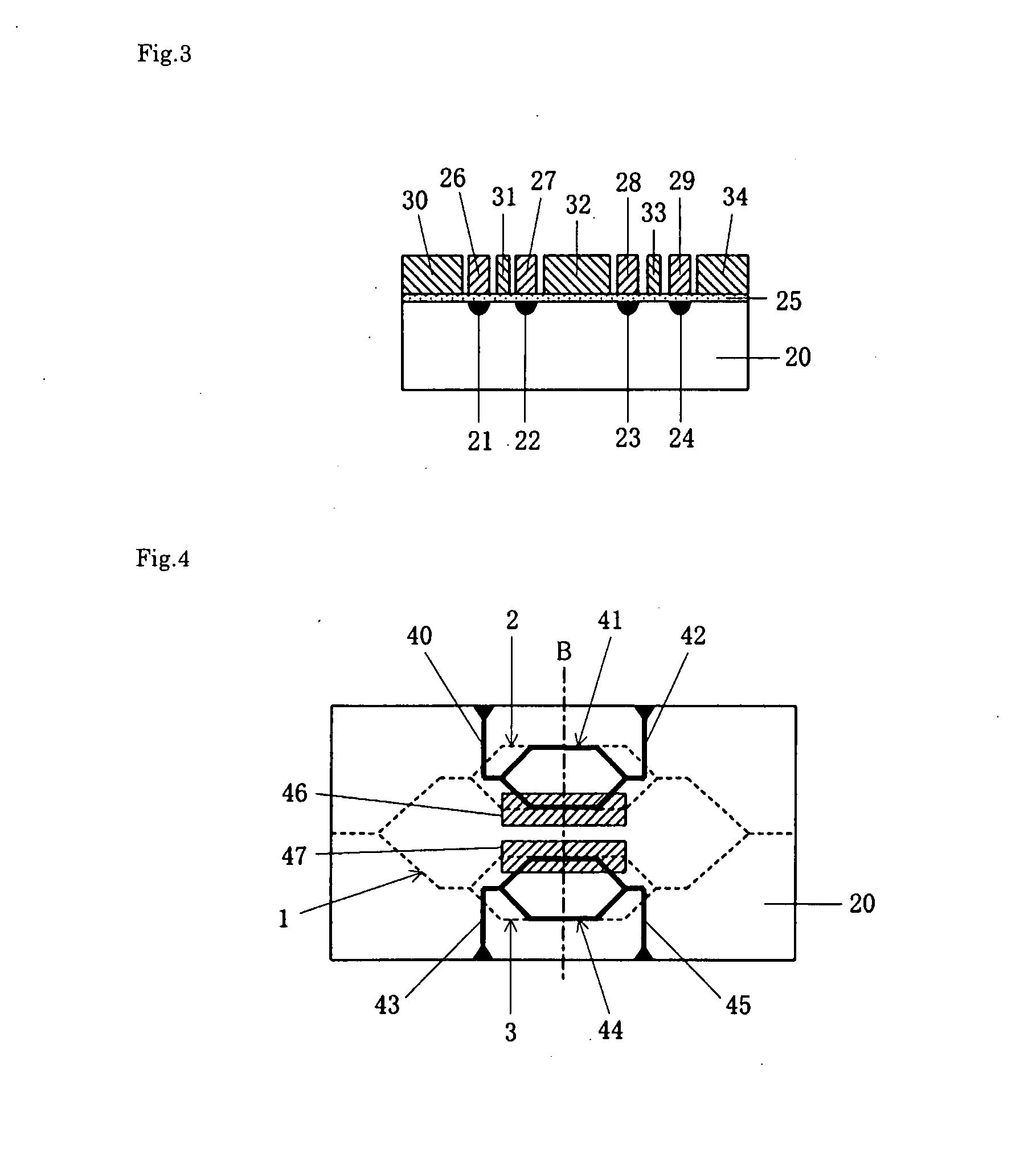
[0032]FIG. 4 is a schematic plan diagram showing the nested modulator according to the present invention, and FIG. 5 is a cross sectional diagram showing the nested modulator along one dot chain line B of FIG. 4.

[0033]The substrate 20 is a substrate having electro-optic effects which is formed of, for example, a lithium niobate, a lithium tantalate, PLZT (lead lanthanum zirconate titanate) or a quartz based material, concretely formed of an X cut plate, a Y cut plate or a Z cut plate of any of these single crystal materials, and in particular, it is preferable to use lithium niobate (LN) or lithium tantalate because it is easy to form an optical waveguide device of which the anisotropy is great. In addition, the below described ease of providing polarization reversal is taken into consideration, and FIG. 5 shows an example where a Z cut plate is used.

[0034]Optical waveguides in such...


PUM


Abstract

A nested modulator is provided where the circuit arrangement of modifying electrodes including signal electrodes is simplified, and at the same time, the drive voltage can be lowered.
A nested modulator, including: a substrate 20 made of a material having electro-optic effects; an optical waveguide formed on the substrate; and a modulating electrode for modulating light waves which are guided through the optical waveguide, wherein the optical waveguide has a main Mach-Zehnder waveguide 1 and sub-Mach-Zehnder waveguides 2 and 3 provided on two branching waveguides of the main Mach-Zehnder waveguide, and the modulating electrode is provided in a sub-branching waveguide of the sub-Mach-Zehnder waveguides, is characterized in that a polarization reversal region 46 or 47 is formed in a portion of a sub-branching waveguide of each of the sub-Mach-Zehnder waveguides, the modulating electrode is formed of signal electrodes including introduced signal electrodes 40 or 43, branching single electrodes 41 or 44 and lead signal electrodes 42 or 45 as well as ground electrodes for each of sub-Mach-Zehnder waveguides, and the branching signal electrodes which branch from the introduced signal electrode are placed so as to work on two sub-branching waveguides for each of the sub-Mach-Zehnder waveguides.

Description

[0001]Priority is claimed to Japan Pat. App. No. 2006-302327 filed Nov. 8, 2006, and the entire disclosure thereof is incorporated herein by reference.BACKGROUND OF THE INVENTION[0002]1. Field of the Invention[0003]The present invention relates to a nested modulator where sub-Mach-Zehnder waveguides are incorporated into the two branching waveguides of the main Mach-Zehnder waveguide.[0004]2. Description of the Related Art[0005]In conventional optical communication technology and optical measurement technology, SSB (single side band) modulators, which are a type of nested modulators where sub-Mach-Zehnder waveguides (hereinafter, referred to as “sub-MZ waveguides”) are incorporated into the two branching waveguides of the main Mach-Zehnder waveguide (hereinafter, referred to as “main MZ waveguide”), are used. As disclosed in the following Patent Document 1, these make it possible to suppress a specific spectrum of the modulated light (discrete spectrum of frequency ω+nΩ, where n is ...

Claims


Application Information

Patent Timeline
IPC IPC(8): G02F1/035
CPCG02F1/035G02F2202/20G02F2201/18G02F2001/212G02F1/212
Inventor ICHIKAWA, JUNICHIROHIGUMA, KAORUYAMAMOTO, FUTOSHIOIKAWA, SATOSHIMORI, SHINGOKURIMURA, SUNAOKITAMURA, KENJIKAWANISHI, TETSUYATSUCHIYA, MASAHIROIZUTSU, MASAYUKI
Owner SUMITOMO OSAKA CEMENT CO LTD
Why Eureka
Try Eureka