Fiber bragg grating and manufacturing method therefor

a fiber bragg and fiber technology, applied in the field of optical fibers, can solve the problems of damage to the surface of optical fibers, difficult to remove only the middle part of a coating layer, and inability to write the grating by irradiating optical fibers, etc., and achieves excellent performance, high degree of reliability, and superior reliability.

Inactive Publication Date: 2008-09-04
FURUKAWA ELECTRIC CO LTD
View PDF5 Cites 10 Cited by
  • Summary
  • Abstract
  • Description
  • Claims
  • Application Information

AI Technical Summary

Benefits of technology

[0019]A fiber Bragg grating according to the present invention is superior in reliability because of being screened at a high level, and dose not need to remove a coating in a middle part for w...

Problems solved by technology

This is because it is occasionally impossible to write the grating by irradiating the optical fiber in a coated state with a laser beam because a resin has an extremely low optical transmittance in a predetermined wavelength region, and also because there is a problem that the resin is burnt to cause deterioration.
However, it is difficult to remove only the middle part of a coating layer, and the method may damage the surface of an optical fiber when removing the coating.
Then, the method causes a problem of lowering the mechanical strength and consequently lowering the reliability.
However, when using such a coating as disclosed in Japanese Patent Application Laid-Open No. 2000-227572, it is only an adoptable manufacturing condition to lower an output level of a...

Method used


Image

  • Fiber bragg grating and manufacturing method therefor
  • Fiber bragg grating and manufacturing method therefor

Examples


examples

[0033]The present invention will now be described in more detail based on examples as embodiment according to the present invention below, but the present invention is not limited to those examples.

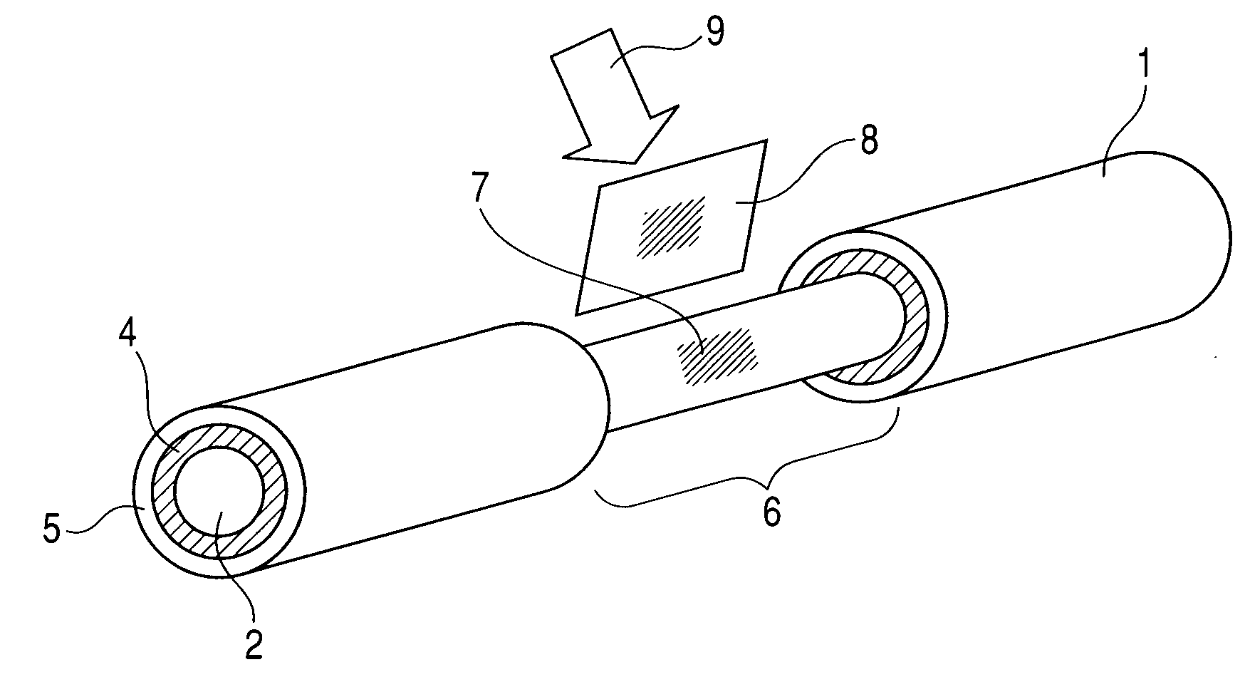
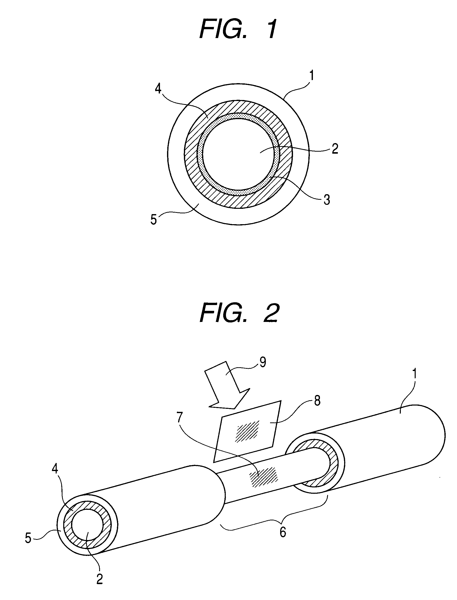
[0034]A super heat-resistant silica coat fiber (a product made by Totoku Electric Co., Ltd.) was used as an optical fiber for a fiber Bragg grating, which composes examples according to the present invention. Exemplified Example 1 is a fiber Bragg grating prepared by the steps of: preparing an optical fiber which has such optical properties and a size as shown in Table 1, and has a glass film containing micro porous bodies formed thereon through the above described steps; and writing a grating thereon. Exemplified Example 2 is a fiber Bragg grating which was prepared by the step of forming a coating layer of a urethane-acrylate-based ultraviolet-curing type resin further on the previous fiber Bragg grating and had an outside diameter of 0.25 mm.

[0035]Comparative examples employed an SM fi...


PUM


Abstract

The present invention provides an optical fiber for a fiber Bragg grating having a high reliability and superior performance. An optical fiber according to the present invention has a glass film containing micro porous bodies formed on the circumference of the optical fiber having a photosensitive core or both of the photosensitive core and a cladding.

Description

BACKGROUND OF THE INVENTION[0001]1. Field of the Invention[0002]The present invention relates to an optical fiber, and relates to an optical fiber having a grating written therein by changing a refractive index in a predetermined region by irradiating the region with ultraviolet light, and a method for manufacturing these optical fibers, in more detail.[0003]2. Related Background Art[0004]The fiber Bragg grating is a device which imparts a different refractive index to a predetermined region of a core or both of the core and a clad, from the other region, by a step of laterally irradiating the predetermined region in a glass part of an optical fiber with a light having a predetermined wavelength from the side of the optical fiber, and which reflects the light having the specific wavelength among lights passing in the optical fiber. As an optical fiber communication technology has progressed in recent years, a network has been sophisticated, signal frequency has been multiplexed, and...

Claims


Application Information

Patent Timeline
IPC IPC(8): G02B6/34
CPCG02B2006/02161G02B6/02104
Inventor ARASHITANI, YOSHIHIROKASHIMA, KAZUHIKOUEMURA, YASUOOKADA, MITSUNORI
Owner FURUKAWA ELECTRIC CO LTD
Why Eureka
Try Eureka